The data for this example comes from C:\arcgis\ArcTutor\GP Service Examples\DriveTimePolygons.
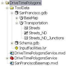
Network Dataset
The ToolData folder contains a file geodatabase, SanFrancisco.gdb. This geodatabase contains a network dataset, Streets_ND, within the Transportation feature dataset. This
network dataset models the street network for the San Francisco area. It provides a
network attribute, DriveTime, which indicates the time taken to travel each street segment.
Basemap
The basemap for this example, SanFranciscoBasemap.mxd, has a layer, Streets, as illustrated below. This layer shows the extent of the network dataset. This means that this task can be used to determine drive–time polygons only in this extent.
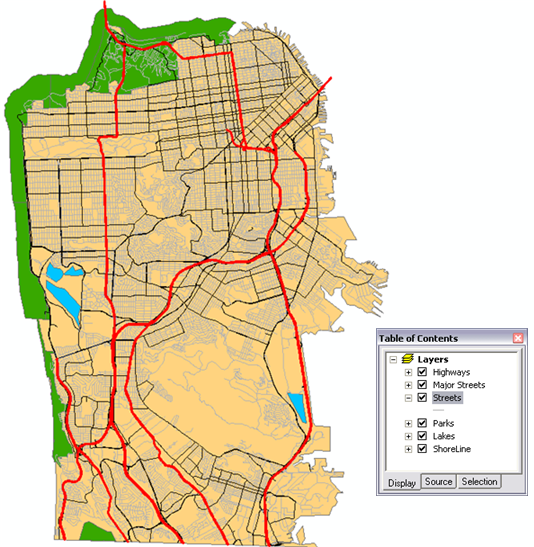
SanFranciscoBaseMap is published as a map service.
Toolbox and map document
The toolbox for the geoprocessing service is DriveTimePolygonsService.tbx, and the source map document for the service is DriveTimePolygonsService.mxd. DriveTimePolygonsService.mxd contains one source data layer, Streets_ND (the network dataset).
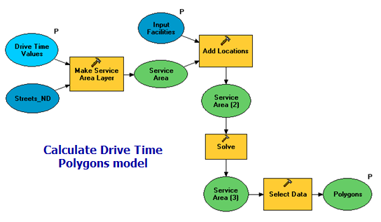
Model overview
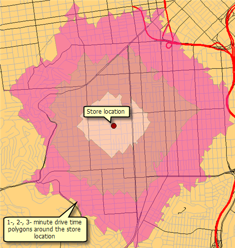
The Calculate Drive Time Polygons model is illustrated below. There are two input variables:
- Input Facilities are the center of the drive–time polygons to be generated. (In network analysis, a facility is any fixed location on the network, such as a building or your current location.)
- Drive Time Values is a space–separated list of drive–time values in minutes.
The model creates a service area network analysis layer, adds the user–digitized points as facilities, and performs a solve to determine the drive–time polygons.
| Element |
Type |
Description |
|---|
| Streets_ND |
Network dataset layer |
The network dataset layer. |
| Drive Time Values |
String, input parameter |
Space–separated list of drive–time values in minutes. |
| Make Service Area Layer |
Tool |
Creates a service area network analyst layer. This layer contains both data and properties that determine how service areas will be calculated, along with the results of the calculation. |
| Service Area |
Network analyst layer |
Service Area layer. |
| Input Facilities |
Feature set (points), parameter |
Point features around which the drive–time polygons are determined. |
| Add Locations |
Tool |
Adds the input facility points to the Service Area layer. |
| Service Area (2) |
Network Analyst layer |
Service Area layer with facilities |
| Solve |
Tool |
Calculates the drive–time polygons. |
| Service Area (3) |
Network Analyst layer |
Service Area layer containing the calculated drive–time polygons. |
| Select Data |
Tool |
Selects the polygons sublayer from the service area layer. |
| Polygons |
Feature layer, output parameter |
The polygons layer from Service Area (3) network analyst layer. |
Network Analysis Workflow
This model illustrates the four step workflow that is common while performing any kind of network analyses.
- Make a network analysis layer.
- Add locations to one or more network analysis classes.
- Solve the network analysis layer.
- Use the results after the solve.
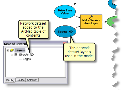
Using the Network Layer
The network dataset for the San Francisco area is added to the map document DriveTimePolygonsService.mxd as a network layer (Streets_ND). This layer is used in the model as an input variable for
Make Service Area Layer tool. Using a network layer greatly improves the overall model execution time since a connection to the network dataset is kept open by the network layer. Otherwise, if the network dataset is referenced from its disk location, a connection to the network dataset is made each time the model executes, which reduces the performance of the geoprocessing service created using the model.
Model Processes
The details about the model follow.
The
Make Service Area Layer tool creates a new Network Analyst layer, ServiceArea, that stores the analysis properties, references the streets_nd network dataset layer used for the analysis, and stores the input facilities and the output polygons. The network dataset has a network cost attribute called Drive Time, which specifies the travel time required to traverse each street segment. This attribute is used as an impedance attribute. The default break values are read from the Drive Time Values variable as a space–separated list of values.
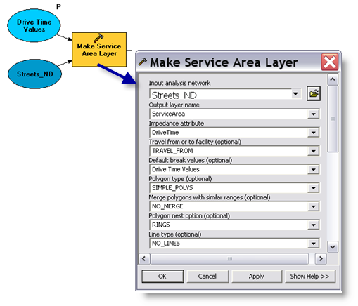
For this service, the NO_MERGE option was used to create overlapping polygons that do not merge for each facility. The RINGS option is used so that, for each drive–time value, the polygons are drawn as rings. This results in the polygons that encompass the area from the previous break up to the cutoff value for the break and do not include the area of the smaller breaks.
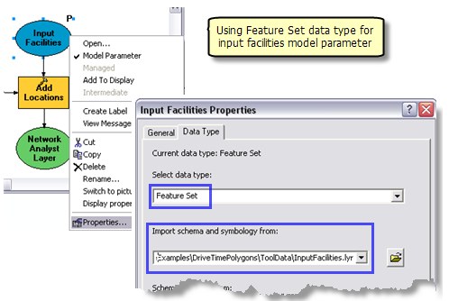
The
Add Locations tool adds the user–digitized points as facilities to the service area layer. The Input Facilities parameter is feature set data type so that the model can interactively accept the user digitized points as facilities. The schema and symbology for the feature set are derived from the InputFacilities.lyr file found within the ToolData folder.
The
Solve tool calculates the service area based on the options specified in the input service area layer and generates the drive–time polygons. The calculated polygons are written to the Polygons sublayer in the output service area layer.
Network analyst layers are not
supported output parameter data types for ArcGIS Server clients. So the
Select Data tool is used to retrieve the polygons sublayer from the Service Area layer. The polygons sublayer is a feature layer data type.
Learn more about the Select Data tool
The Create Drive Time Polygons tool layer is created by dragging and dropping the model into the ArcMap table of contents. You should test the model before publishing as follows:
- Create the tool layer.
- Right-click the tool layer and click Open. The tool dialog opens.
- Enter a point and drive–time distances, then click OK.
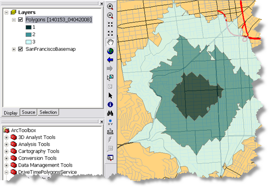
- The drive–time polygons are added as a sublayer to the tool layer.
The output of the Create Drive Time Polygons model is a feature layer. When a feature or raster layer is output by model, the output layer is added to the tool layer as is, meaning symbology you define in the tool sublayer is ignored. You can try the following experiment to confirm this.
- After opening and executing the tool layer, right-click the polygon sublayer and click Properties.
- Click the symbology tab.
- Change the symbology to a single symbol (a blue polygon fill, for example).
- The polygon sublayer is now drawn with a single color instead of graduated colors.
- Open the tool layer and execute.
- The polygon sublayer is drawn with graduated colors.
As explained in the topic
Defining output symbology for geoprocessing tasks, when a model outputs a layer, the symbology found in the layer takes precedence over tool layer symbology. The reason for this rule is that some tools, like Service Area layers, output layers containing custom symbology. In order to preserve this custom symbology, the symbology in the tool sublayer is ignored. If you want to change symbology of the drive–time polygons, the Create Drive Time Polygons model will need to output a feature class instead of a feature layer. This is easily accomplished by adding the
Copy Features tool to the model, using the Polygon variable as input to Copy Features.
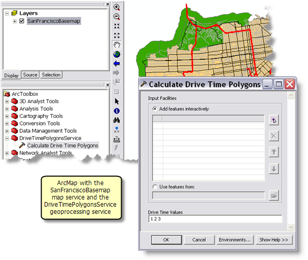
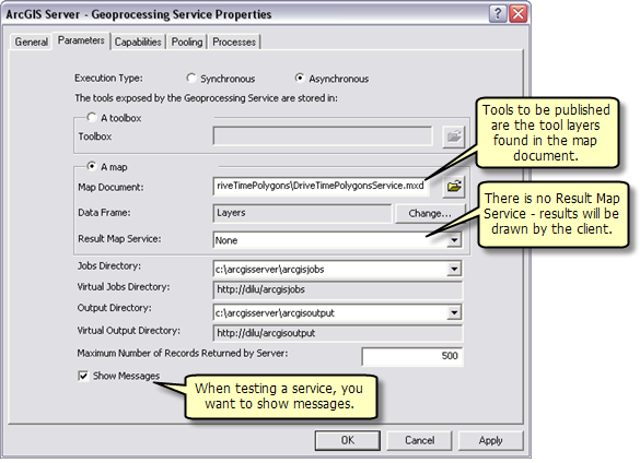
SanFranciscoBaseMap.mxd is published as a map service. DriveTimePolygonsService.mxd is published as a geoprocessing service with no result map service, as follows:
- In ArcCatalog, right-click SanFranciscoBaseMap.mxd and click Publish to ArcGIS Server.
- Accept all defaults.
- In ArcCatalog, navigate to your server, right-click and choose Add New Service. Name the service DriveTimePolygonsService and choose Geoprocessing Service as the type.
- Click Next.
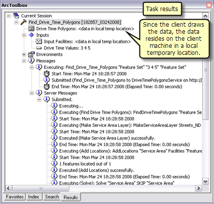
- In the next panel you choose Asynchronous for Execution type. For the tools exposed by the Geoprocessing service are stored in option, select A Map option and specify DriveTimePolygonsService.mxd for the Map Document. Since you will test your service, check Show Messages.
- Click Next. From this point on, you can accept the default values provided by the wizard and create the service.