Editing and data compilation > Getting started with editing
Using the snapping environment |
|
|
Release 9.2
Last modified August 17, 2007 |


Print all topics in : "Getting started with editing" |
About the snapping environment
The snapping environment can help establish exact locations in relation to other features. Suppose you're creating a new segment of an electric line that begins from an existing transformer; you want to ensure that the vertex of the line connects precisely to the transformer. The snapping environment makes this type of task accurate and easy.
The snapping environment can also be used to move a feature to a precise location in relation to another feature. For example, you can move a parcel and have one of its corners jump, or snap, precisely to a corner of another parcel. Simply move the parcel's selection anchor to its corner vertex after setting the appropriate snapping properties. Then move the parcel toward its new location until the selection anchor snaps to the corner vertex of the other parcel.
Setting the snapping environment involves setting a snapping tolerance, snapping properties, and a snapping priority. The snapping tolerance is set on the General tab of the Editing Options dialog box (Editor menu > Options), while snapping properties and priority is set on the Snapping Environment dialog box (Editor menu > Snapping).

Learn about how representations work with the snapping environment
The snapping tolerance
The snapping tolerance is the distance within which the pointer or a feature is snapped to another location. If the element being snapped to—such as a vertex or edge—is within the distance you set, the pointer automatically snaps to the location.
You set the default snap tolerance value in map units or pixels on the General tab of the Editing Options dialog box (click Editor, then click Options). When editing, press the T key to see a circle representing the snap tolerance, shown in green on the graphic below.
![]()
You can also interactively set the snap tolerance, using the Snap Tolerance tool ![]() . This tool is not on the ArcMap user interface by default, but you can add it to any ArcMap toolbar from the Editor category on the Commands tab of the Customize dialog box. To set the snap tolerance with the Snap Tolerance tool, click the map and drag the mouse pointer to draw a circle.
. This tool is not on the ArcMap user interface by default, but you can add it to any ArcMap toolbar from the Editor category on the Commands tab of the Customize dialog box. To set the snap tolerance with the Snap Tolerance tool, click the map and drag the mouse pointer to draw a circle.
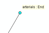
Another useful trick for working with snapping is to enable SnapTips, which is a small piece of text that pops up to show what you are snapped to. In the graphic below, the mouse pointer has snapped to an end element in the arterials layer.

To see SnapTips, check Show SnapTips on the General tab of the Editing Options dialog box. Once you have snapped to an element, the cursor needs to be stationary for at least one second for the tip to appear. The tip will fade after several seconds. The SnapTip is also shown in the ArcMap status bar at the bottom of the application.
The snapping properties
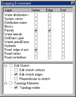
You can choose the part of the feature, vertex, edge, or endpoint to which you want your new feature to snap by setting the layer snapping properties. To make your new feature (a segment of primary) snap to the vertex of an existing transformer in the transformers layer, check the box under Vertex and next to the transformers layer in the Snapping Environment window. When the pointer comes within the snapping tolerance of the transformer, the first vertex of the primary snaps to the vertex of the transformer.
Snapping to edit sketch and topology elements
You can also set snapping properties that apply specifically to an edit sketch or topology elements. These properties are located at the bottom of the Snapping Environment window.
Checking the Edit sketch vertices box allows you to snap to vertices in the sketch. With Edit sketch edges, you can snap to the edge or boundary of segments in the sketch. You can check Perpendicular to sketch to snap to a 90-degree angle from the last segment in the sketch. To snap to topology elements, check the box next to Topology nodes.
View a table of snapping properties
The snapping priority
You can also set the snapping priority for layers on your map. The order of layers listed in the Snapping Environment window determines the order in which snapping will occur. Snapping occurs first in the layer at the top of the list, then in each consecutive layer down the list. You can easily change the snapping priority by dragging the layer names to new locations.
The Snap to Feature command
Apart from the rules set in the snapping environment, you can also snap on the fly to specific features. This is done through the Snap to Feature command located on the Sketch tool context menu.
By specifying a feature and the part of the feature to which you wish to snap, your next vertex will automatically be placed regardless of the Snapping Environment settings.
How to use the snapping environment
Setting the snapping tolerance
- Click the Editor menu and click Options.
- Click the General tab.
- Click the Snapping tolerance drop-down arrow and click the type of measurement unit you want to use for snapping tolerance—pixels or map units.
- Type the desired number of measurement units in the Snapping tolerance text box.
- Click OK.
| Tips |
|
Setting the snapping properties
- Click the Editor menu and click Snapping.
- Check the snapping properties you want.
The Snapping Environment window appears.
The snapping properties are effective as soon as they are checked or unchecked.
| Tip |
|
Setting the snapping priority
- Click the Editor menu and click Snapping.
- Click and drag the layer names to arrange them in the order in which you want snapping to occur. (The first layer in the list will be snapped to first.)
The Snapping Environment window appears.
The snapping priorities you set are effective immediately.
| Tip |
|
Snapping to a specific feature
- Click the tool palette drop-down arrow and click the Sketch tool
 .
.
- Right-click the feature you want to snap to, point to Snap to Feature, and click either Endpoint, Vertex, Midpoint, or Edge. This will place a vertex at the nearest location that matches your choice.
If nothing happened, move the mouse closer to the element to you want to snap to, and try again.