Using the Data Interoperability tools |
|
|
Release 9.3
Last modified June 29, 2009 |


|
This section provides an overview of the tools that are available in the Data Interoperability extension for accessing your various data formats. These tools can be organized into three functional areas:
- Direct read
- Quick conversion
- Data transformation
Which tool you should use depends on your project requirements and objectives. For example, you may only need to directly read nonnative data formats, and installing the extension is all you need for this capability. On the other hand, you may need to convert your data to a native ESRI format to perform tasks such as editing or creating a topology. For this, you could use the Quick Import geoprocessing tool or create your own custom tool with the Spatial ETL tool. Lastly, you may need to convert and manipulate your data to generate an output that is tailored to your project or a client's particular needs. The Data Interoperability extension provides the framework to support all of these types of workflows.
Direct read tools
The simplest way to directly read external ESRI data formats is by browsing to the datasets in the Catalog tree in ArcCatalog. This ability only requires that the Data Interoperability extension is enabled. How the data is represented in the Catalog tree will depend on the format of the data—some data will be containers with feature classes (like a coverage) and others will be single files (like a shapefile). The following illustration shows several different data formats in the Catalog tree:
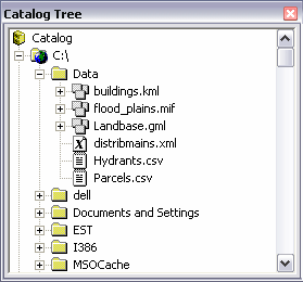
As with ArcCatalog, you can also easily access data formats that are not from ESRI in ArcMap via the Add Data browser. Any folder that contains these data sources will be displayed and available for use. Simply add these data sources to your map to integrate them into your query, analysis, and cartographic workflows. The following illustration shows several different data formats in the Add Data browser:
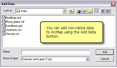
Interoperability connections
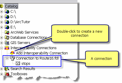
Another method for directly reading external ESRI data formats is to use interoperability connections. A connection provides a more robust method for directly reading your data sources. It allows you to make a connection to a data source or a collection of data sources.
Once the connection is made, data sources will appear underneath the Interoperability Connection entry in the Catalog tree, as illustrated below. A connection is just like any other dataset in that you can add it to ArcMap or use it in geoprocessing tools.
Here are some reasons why you may want to use an interoperability connection:
- Maintain database connections.
- View formats with nonstandard file extensions that not be recognized by the Catalog tree.
- Aggregate many tiles of data.
- Add formats that require parameters like user names and passwords.
- Specify the coordinate system.
Double-clicking Add Interoperability Connection will open the Interoperability Connection dialog box, where you choose the dataset and the format you want to work with. You can also modify the coordinate system and specify settings that are particular to the data source.
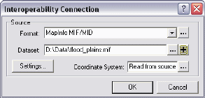
Clicking the Format's browse button
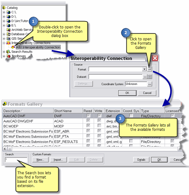
Learn more about creating custom formats.
The Settings button opens an input settings dialog box that allows you to customize the connection to your source data. The appearance and content of the input settings dialog box will vary depending on the data format you are working with. Some settings, such as user name and password, may be required to establish a database connection. This varies depending on the format.
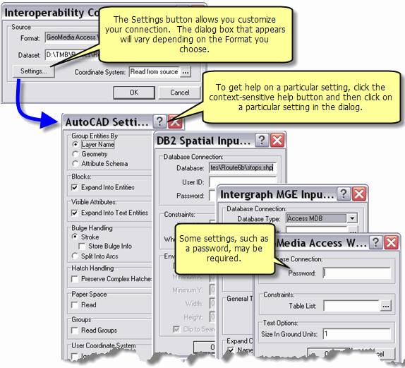
When you have chosen your data format, source data, input settings, and coordinate system, a new interoperability connection will be established. The data source will now appear under Interoperability Connections in the Catalog tree and is available for use throughout ArcGIS.
Quick conversion tools
The Data Interoperability extension comes with the Quick Import and Quick Export geoprocessing tools to quickly convert data. These tools are intended for simple data translations where the number of input features will match the number of output features. This is known as a one-to-one translation or flat conversion. Both tools reside in the Data Interoperability Tools toolbox. To open the tool's dialog box, double-click the tool, or right-click the tool and choose Open.
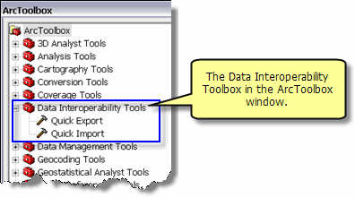
These tools are ideal for scenarios where you need to convert data quickly. Both tools can be incorporated in a geoprocessing model or script, allowing you to combine a conversion with other geoprocessing operations. It is important to note that Quick Import and Quick Export will not modify feature geometry or schemas during the conversion.
Quick Import
The Quick Import tool allows you to convert input data to a geodatabase. Double-clicking the tool will open the Quick Import dialog box where you can specify the input dataset and output staging geodatabase.
What is an output staging geodatabase?
The output staging geodatabase is the name of new geodatabase that will be created to contain the converted output. The composition of the output is entirely dependent on the contents of the input data and its format. For some data and formats, the output may be a single feature class, but for other formats there may be several feature classes and tables, some of which you may decide you don't need. For this reason, the output geodatabase is referred to as a staging geodatabase, in anticipation that you'll copy certain feature classes and tables from the staging geodatabase to a more permanent location, then, at some future point, delete the staging geodatabase.

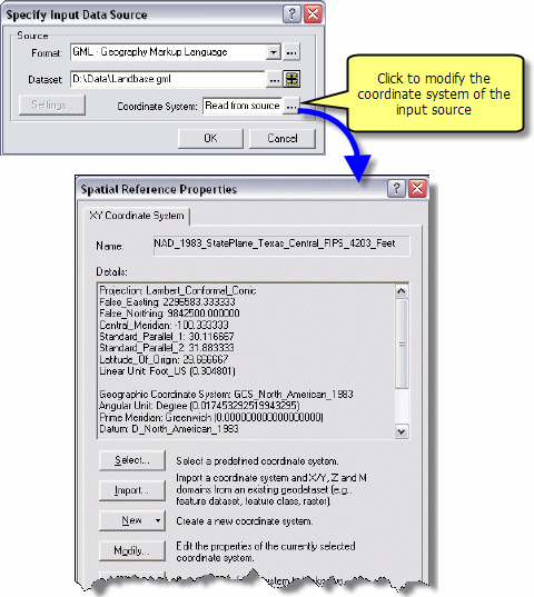
Clicking the Input Dataset browse button

You can click the drop-down arrow to choose a data format or click the browse button
Once you have chosen a data format and source dataset, you can modify the settings by clicking the Settings button, which opens an input settings dialog box. The appearance and contents of this dialog box vary depending on the data format. For some data formats, modifying these settings is optional. However, other data formats have required settings such as for establishing database connections.

The coordinate system of the input data source can be modified. By default, the coordinate system is set to Read from source, meaning that the input data source's coordinate system will be used. This can be changed by clicking the Coordinate System's browse button
When an input dataset, output staging geodatabase, settings, and coordinate system information have been specified, execute the tool by clicking the OK button. The end result will be a new geodatabase containing the converted data.
Quick Export
The Quick Export tool, shown below, allows you to convert layers to an output dataset.
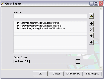
To choose input layers, click the Input Layer browse button to open the Input Layer browser. (The Quick Export tool allows you to enter multiple layers. Click here to learn more about using tools that allow multiple inputs.) Click the Output Dataset browse button to open the Specify Output Data Destination dialog box, as shown below. This dialog box is essentially the same as the Specify Input Data Source dialog box shown in the Quick Import tool above.
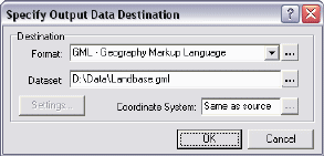
You can either click the drop-down arrow to choose a data format or click the browse button
After choosing a data format and destination dataset, click Settings to modify the output settings. The appearance and contents of the Output Settings dialog box will vary depending on the data format.
The coordinate system of the output data source can be modified during the Quick Export process. By default, the coordinate system is set to Read from source, meaning that the output data source's coordinate system will be used. This can be changed by clicking the Coordinate System's browse button. This will open the Spatial Reference Properties dialog box and allow you to choose a different coordinate system.
When an input layer(s), output dataset, settings, and coordinate system information have been specified, the tool can be executed by clicking the OK button. The end result will be an output dataset in the specified data format.
Data transformation tools
Data transformation tools are used to manipulate and transform data. They can perform both schema and geometric restructuring as you convert data to a new output data source. For example, you can add, remove, or rename attributes, and calculate or assign values to new or existing attributes. These tools allow you to integrate complex data model restructuring within the geoprocessing environment.
The FME Workbench application is included with the ArcGIS Data Interoperability extension. This application is a visual diagramming environment that supports dozens of transformers that enable you to transform both geographic and attribute information. These tools use Safe Software's feature manipulation language of their Feature Manipulation Engine (FME), which gives you full control of the data translation and transformation process.
Spatial ETL
The Spatial ETL tool provides data transformation capabilities within the geoprocessing environment. It replaces the three custom tools (Custom Data Import, Custom Data Export, and Custom Data Transformation) that were available in previous versions of ArcGIS 9.x. Since Spatial ETL provides a single tool for all of your data transformation workflows, it can be used for importing, exporting, and transforming data.
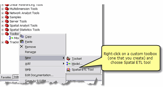
The Spatial ETL tool uses a wizard to guide you through the process of choosing the source data format and dataset, as shown below.
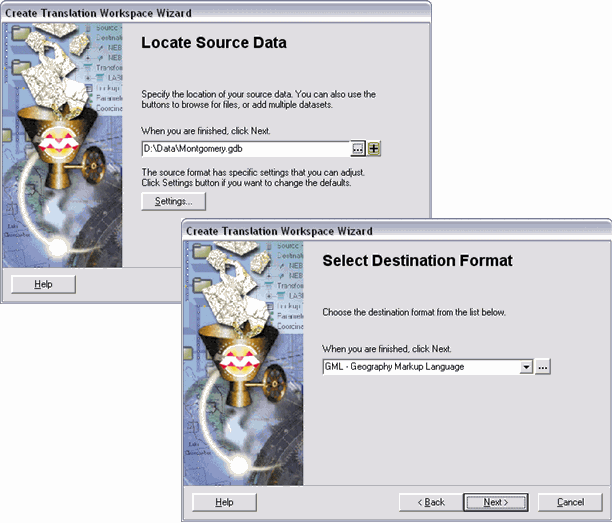
Once the source data format and dataset have been specified, the wizard will prompt you to choose a destination format.
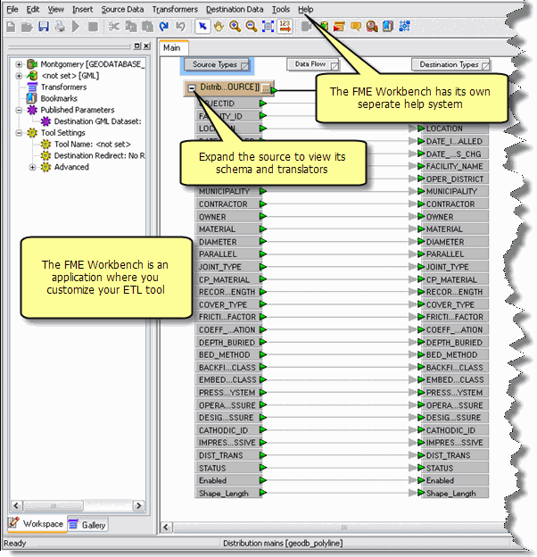
The wizard also prepares your FME Workbench environment, known as the workspace, by automatically creating source and destination data items based on your input. The following illustration shows an example of how your workspace will appear after finishing the wizard. At this point, there is only one connection between the source and destination data. You can add transformers and additional datasets to extend your data transformation workflow.
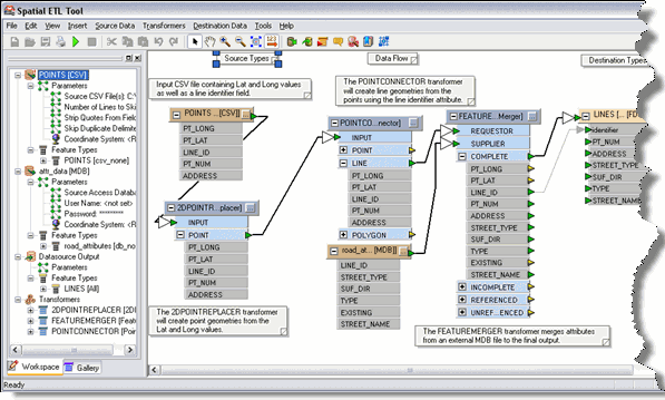
The illustration below shows a workspace that contains several source and destination datasets and defines a custom data transformation.
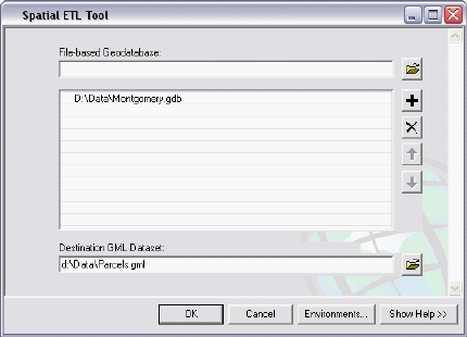
When the workspace edits are completed and saved, you'll have a new tool in your toolbox. It can be run as a stand-alone tool by double-clicking the tool, or incorporated into models or scripts. The illustration below shows the tool dialog box.
When the tool is executed, a new dataset will be generated in the data format and location you specified.