Extensions > Network Analyst > Network dataset concepts
Understanding connectivity |
|
|
Release 9.3
Last modified March 2, 2010 |


Print all topics in : "Network dataset concepts" |
When you create your network dataset, you will make choices that determine which edge and junction elements are created from source features. Ensuring that edges and junctions are formed correctly is important for accurate network analysis results.
Connectivity in a network dataset is based on geometric coincidences of line endpoints, line vertices, and points and applying connectivity rules that you set as properties of the network dataset.
Learn more about setting and modifying connectivity when creating and editing network datasets.
Connectivity groups
Connectivity in ArcGIS Network Analyst begins with the definition of connectivity groups. Each edge source is assigned to just one connectivity group and each junction source can be assigned to one or more connectivity groups. Junctions that are assigned to two or more connectivity groups provide the only way that edges in different connectivity groups can connect. Connectivity groups are used to model multimodal transportation systems. For each connectivity group, select the network sources that interconnect. In the subway and street multimodal network example below, metro lines and metro entrances are all assigned to the same connectivity group.
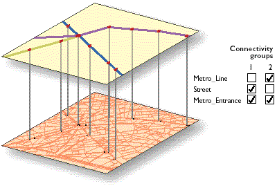
Note that Metro_Entrance is present in both connectivity groups. It forms the link between the two connectivity groups. Any path between the groups must travel through a shared metro entrance. For example, a route solver may determine that a pedestrian's best route between two locations in a city is to walk on the street to a metro entrance, board a subway train, take another train at a line-crossing station, and exit through another metro entrance. Connectivity groups keep the two networks distinct yet connect them at shared junctions (metro entrances).
Connecting edges within a connectivity group
Edges in the same connectivity group can be made to connect in two ways, set by the connectivity policy on the edge source.
- If you set "endpoint" connectivity, then line features become edges joining only at coincident endpoints.
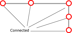
- If you set "any vertex" connectivity, line features are split into multiple edges at coincident vertices. Setting this policy is important if your street data is structured such that streets meet other streets at vertices.

In this case, line feature l1 becomes edge element e1 and line feature l2 becomes edge element e2. There will always be one edge element created for one line feature with this connectivity policy.
Building networks with endpoint connectivity is one way to model crossing objects such as bridges. To model this case, the two sources, bridges and streets, are placed in the same connectivity group (1). The Streets source is assigned any vertex connectivity to allow street features to connect to other street features at coincident vertices. The Bridges source is assigned endpoint connectivity. This means bridges connect to other edge features only at their endpoints. Consequently, any street going under the bridges will not be connected to the bridge. The bridge will connect to other streets at its endpoints.
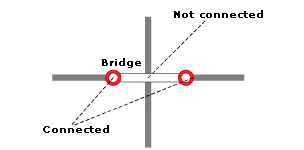
If you have only one source in your network that you want to use to model overpasses (bridges) and underpasses (tunnels), you could consider using elevation fields on planar data. For more information, see the Elevation fields section, below.
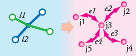
In this case, two polylines crossing at a shared vertex position will be split into four edges, with a junction at the vertex. Edges e1 and e2 are identified with the source feature class and object ID of line feature l1. Edges e2 and e4 are identified with the source feature class and object ID of line feature l2. Junction j3 will be a newly created system junction. Junctions j1, j2, j4, and j5 will be either system junctions or junctions from coincident points from a source feature class.
Not all crossing line features can produce connected edges. If they do not share any coincident endpoints or vertices, no connectivity policy will create a junction at the point of intersection. Street data for network datasets must be cleaned first so that either vertices or endpoints are present at all intended junctions.

If you need to remedy your street data, either use a geoprocessing tool such as Integrate to split crossing lines or establish a topology on these feature classes and edit street features while applying topology rules that enforce feature splits at intersections.
Learn more about the Integrate tool.
Learn more about topology.
Connecting edges through junctions across connectivity groups
Edges in different connectivity groups can be connected only through a junction shared by the connectivity groups.
In the example of a multimodal system combining a bus network and street network, a bus stop is added from a point source and is in both connectivity groups. The point location of the bus stop must be spatially coincident with the bus lines and street lines it joins. When the point location for the bus stop is added, whether or not it successfully becomes a junction depends on the junction connectivity policy. As with edges, junctions connect to edges at endpoints or vertices, depending on the target edge source's connectivity policy. However, there are situations in which you may want to override this behavior.
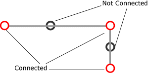

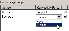
For example, the bus line to which the bus stop connects has an endpoint connectivity policy, but often you will want to place the bus stop at an intermediate vertex. To do so, you will need to set a junction policy to override the default behavior of connecting a junction to a given edge.
To override the default behavior of junctions forming at endpoints or vertices according to the edge source's connectivity policy, set the junction source's connectivity to override. The default is to honor the edge connectivity policy.
Elevation fields
Elevation fields are used to model connectivity in ARC/INFO, ArcView GIS, and ArcGIS. ArcGIS Network Analyst supports this connectivity model. Elevation fields are used in the network dataset to refine the connectivity at line endpoints. They contain elevation information derived from fields on a feature class participating in the network. This is different from establishing connectivity based on Z elevations, in which the physical elevation information is stored on each vertex of the feature. Elevation fields apply to edge and junction sources. Edge feature sources using elevation fields have two fields to describe elevation (one for each end of the line feature).
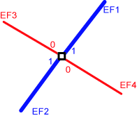
In the example below, four line features (EF1, EF2, EF3, and EF4) belong to the same connectivity group and observe endpoint connectivity. The elevation values for EF3 and EF4 are 0; the elevation values for EF1 and EF2 are 1. Hence, at the point of intersection, EF3 is connected to EF4 only (not to EF1 or EF2). Similarly, EF1 connects to EF2 only, not to EF3 or EF4. It is important to understand that the elevation fields refine the connectivity. They do not override it. Two edge elements may have the same elevation field value and may be coincident, but if they are placed in two different connectivity groups, they will not be connected.
Numerous data vendors provide elevation field data to model connectivity. The ArcGIS network dataset connectivity model can use this elevation field data to enhance the connectivity. The interaction of elevation fields with the connectivity model is also vital to model special scenarios such as bridges and tunnels.