Network analysis > Analyzing geometric networks > Creating and managing geometric networks
About creating geometric networks |
|
|
Release 9.3
Last modified July 14, 2009 |


Print all topics in : "Creating and managing geometric networks" |
NOTE: Although geometric networks can be both created and edited in ArcInfo and ArcEditor, they are read-only in ArcView.
A geometric network is a connectivity relationship between a collection of feature classes in a feature dataset. Each feature has a role in the geometric network of either an edge or a junction. Multiple feature classes may have the same role in a single geometric network.
The basic methodology for creating a geometric network is to determine which feature classes will participate in the network and what role each will play. Optionally, a series of network weights can be specified, as can other more advanced parameters.
Two methods are available for creating a network: creating a new, empty geometric network and building a geometric network from existing simple features.
Creating a new, empty network
Geometric networks are created inside feature datasets. Once a geometric network has been created, you must add feature classes to the feature dataset for that geometric network and assign them roles in the network.
ArcCatalog lets you create a new geometric network from nothing, then design and build up the network from scratch. You can then use editing tools in ArcMap, custom Visual Basic (VB), Visual Basic for Applications (VBA), or C++ code to add features to the geometric network. New feature classes can be added to a geometric network at any time.
The process of creating a network can be summarized in the following steps:
- Use ArcCatalog to create the feature dataset that will contain the geometric network and its feature classes.
- Use ArcCatalog to create an empty geometric network in the feature dataset (shown below; see "How to create a new geometric network").
- Use ArcCatalog to create new feature classes in the feature dataset and assign each a role in the geometric network.
- Use ArcCatalog to establish connectivity rules for elements of the geometric network.
- Use custom scripts or editing in ArcMap to add features to the network.
Building a geometric network from existing data
You may already have data from which you want to create a geometric network in your geodatabase. ArcCatalog and ArcToolbox contain tools to create a geometric network from that data.
The process of building a geometric network from existing data can be summarized in the following steps, all performed in ArcCatalog:
- Import data into new or existing feature classes.
-
Build a geometric network from the feature classes.
-
Establish connectivity rules for the geometric network.
How geometric networks are built
You may already have data from which you want to create a geometric network in your geodatabase. ArcCatalog and ArcToolbox contain tools to create a geometric network from that data.
The process of building a geometric network from existing data can be summarized in the following steps, all performed in ArcCatalog:
- Import data into new or existing feature classes.
- Build a geometric network from the feature classes.
- Establish connectivity rules for the geometric network.
Geometric network snapping models
Ideally, your data should be clean before you build a network. Clean data means that all features that should be connected in the network are geometrically coincident—that is, no overshoots or undershoots. However, if this is not the case, the data may be snapped during the network building process.
It is important to understand how connectivity is established based on snapping during the network building process and how feature geometries are adjusted to establish that connectivity. The following is a series of examples of how connectivity is established in given scenarios.
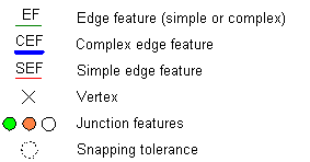
In these diagrams, use the key below to identify what types of features are illustrated in each scenario:
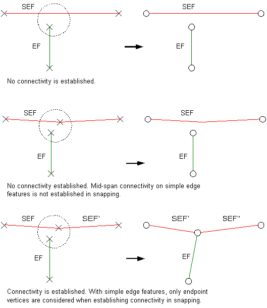
Simple edges connectivity model
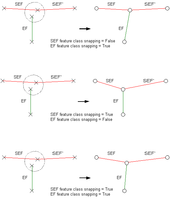
Simple edges: Connectivity against simple edges is established only at the ends of edge features. Mid-span connectivity will not be established even if there is a vertex along the simple edge feature.
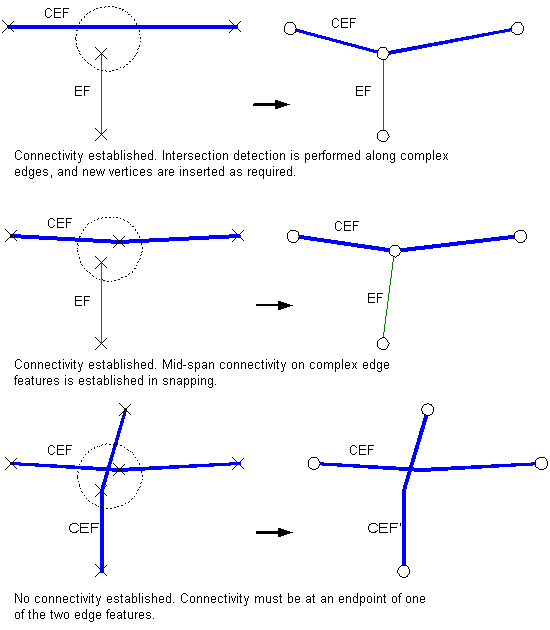
Complex edges connectivity model
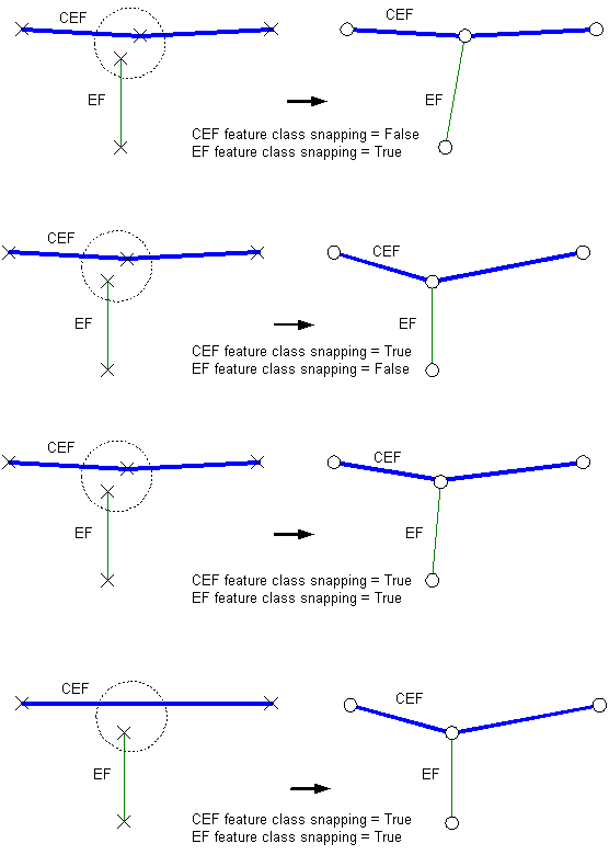
Complex edges: Connectivity against complex edges is established both at the ends of features and mid-span. If there is no vertex along the complex edge where connectivity is established, a new vertex is created. When snapping complex edges, connectivity must be at the endpoint of at least one of the edges. Connectivity will not be established between the mid-span of one edge and the mid-span of another edge.
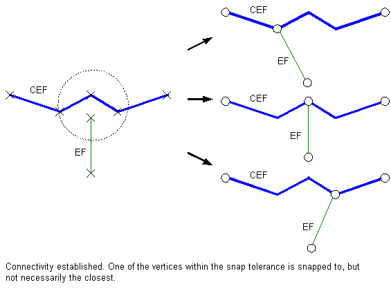
Vertex clustering connectivity model
Vertex clustering: When snapping two features, if there is more than one vertex within the snapping tolerance, then those vertices are treated as a cluster. Snapping will occur to one of the vertices in the cluster but not necessarily the closest one.
Coincident junctions connectivity model
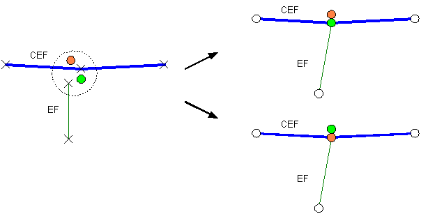
Coincident junctions: When the network building process encounters coincident junctions or when the snapping process results in coincident junctions, the resulting connectivity will be nondeterministic. In other words, connectivity will only be established to one of the coincident junctions.
Adjusting features
When snapping features during network building, it is important to understand how the geometry of features is adjusted when snapping. All or part of any feature in a feature class that was specified as being adjustable in the Build Geometric Network wizard can be moved. Those features in feature classes that are not adjustable will remain fixed throughout the network building process.
All features in all feature classes have equal weights when being adjusted during snapping. This means that if the endpoints for two edges need to be snapped and both features can be adjusted, then they will move an equal distance to snap together. If one of the features is not adjustable, then only the adjustable feature will move to snap to the static feature.
Network building errors
When building a geometric network from existing simple feature classes, illegal network geometries may be encountered in some of the input feature classes. Instead of failing when an illegal geometry is encountered, the network builder creates an instance of the feature as a network feature but will not create any network connectivity for that particular feature. If this occurs, a warning message is displayed at the end of the network building process, and a table is created in the database to record these errors.
The warning message will report the total number of illegal features in each network feature class. The error table's name will be <geometricnetwork_name>_BUILDERR. The network building error table's schema is shown in Network build errors table schema.
ArcMap has tools that allow you to use the network build error table to identify these illegal features (see Identifying geometric network build errors). Once you have identified the features and repaired their geometries to be legal geometries, you can use the Rebuild Connectivity tool to repair the network connectivity for those features (see About editing geometric network features).
The network build error table will only show those features that have illegal network geometry at the time the network was built. If you repair these features, or if other features are created in the network with illegal geometries, the network build error table will not be updated. Once you have fixed the geometry of the features reported in this table, it is no longer needed and can be deleted using ArcCatalog.
There are a number of tools and commands in ArcMap to help you identify and repair network features with illegal geometries and with inconsistent network connectivity.
Click the links below to learn more about these tools and commands:
Learn about editing geometric network features.
Verify Network tools and commands.
Schema locking
An exclusive lock is required on all the input feature classes when building a geometric network. If any of the input feature classes has a shared lock, the network will not be built.
If any of the feature classes in a network has a shared or exclusive lock, that lock is propagated to all the other feature classes in the network.
Learn more about exclusive locks and schema locking.