A schema (sometimes known as "data model") can be described as the structure of a dataset, or more accurately a formal definition of a dataset’s structure.
Each dataset has its own unique structure (schema) which includes feature types, permitted geometries, user-defined attributes and other rules that define or restrict its content.
When you create a new workspace, FME reads the source dataset and creates a workspace definition of the schema. Generally it will also create a destination schema, that is, a definition of the structure of the destination dataset. Destination schemas could be called "logical" schemas since they don’t physically exist at that point.
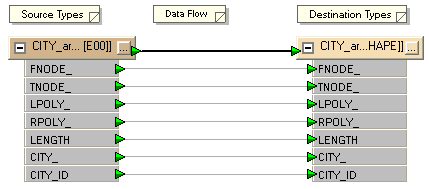
Here is a source and destination schema as they appear in Workbench. Source data is on the left, and destination data is on the right.

Each item is a separate feature type. Here there is one source and one destination feature type, and each feature type has a set of attributes.
A new workspace will usually have identical source and destination schemas; but this is not always possible – particularly when the source and destination formats are different. In these circumstances, FME will attempt to compensate for any differences between source and destination schema. The workspace can then be edited and the destination schema changed as required; for example attributes can be added, removed or renamed.
One of the real powers of FME is the ability to edit destination schemas and transform data to match during processing.
A schema is made up of many components. Some of these relate to a dataset as a whole; for example feature types belonging to a dataset are regarded as part of the overall schema and are depicted in the Workbench canvas window.
However, some parts of the schema relate specifically to a single feature type only. Attributes are one such component. These components are shown in the properties dialog of a feature type.
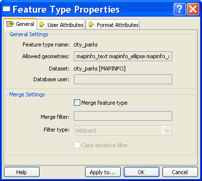
Above: The Feature Type Properties dialog has a number of tabs to display information.
Under the General tab there is the name of the feature type, in this case city_parks. Permitted geometry types are shown here, as is the name of the parent dataset for the feature type.
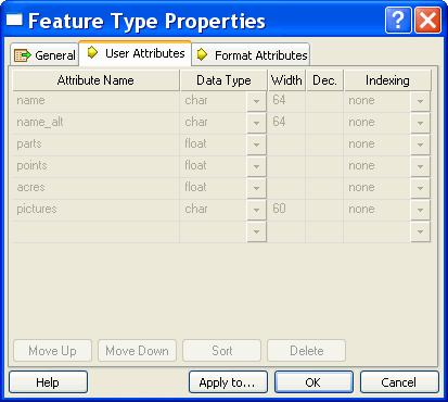
Above: The User Attributes tab shows a list of attributes present the feature type. Each attribute is defined by its name, data type, width and number of decimal places.
This example shows a source feature type (you can't edit the attributes). Source attributes cannot be edited because this is a representation of the physical schema of the data; if they were changed the schema would no longer match the source dataset.
The attributes on a destination dataset can be edited, to create the required output.
The Data Type column for an attribute shows only values that match the permitted types for that data format. For example, an Oracle destination schema permits attribute types of varchar or clob.
The default schema that FME creates is one suitable for a Quick Translation. When there is a need to customize the output schema, edits can be made using Workbench.
Schema editing is the process of altering the destination schema to customize the structure of the output data. One good example is renaming an attribute field in the output.
You can edit a number of things, including (but not limited to):
Rename an Attribute: Any attribute on the destination schema can be renamed. To rename an attribute open the Feature Type Properties dialog and click the ‘User Attributes tab. Click the attribute to be renamed and enter the new name.
Change an Attribute Type: Any attribute on the destination schema can have a change of type, for example changing ID from an integer to a float. To change an attribute type open the Feature Type Properties dialog and click the User Attributes tab. Use the Data Type field to change the type of an attribute.
Rename a Feature Type: To rename a destination feature type (for example rename roads to updated_roads) open the Feature Type Properties dialog. Click the General tab. Click in the Feature Type name field and edit the name as required.
Change a Geometry Type: To change the permitted geometry for a feature type, (for example change the permitted geometries from lines to points) open the Feature Type Properties dialog. Click the General tab. Choose from the list of permitted geometries. This field will be greyed out where the format permits any geometry type.
Change a Dataset (Move a Feature Type): When more than one destination dataset is defined, you can switch a feature type from one destination dataset to another, using the drop-down list under the General tab.
Schema Mapping is the means by which a datasets structure can be transformed.
In FME Workbench, one side of the workspace shows the source schema (what we have) and the other side shows the destination schema (what we want). Schema mapping is the process of connecting the source schema to the destination schema in a way that ensures the right source features are sent to the right destination feature types and the right source attributes are sent to the right destination attributes.
Feature mapping is the process of connecting source feature types to destination feature types.
Attribute Mapping is the process of connecting source attributes to destination attributes.
Below: A source feature type in a Shape dataset (roads) is connected to a destination feature type in a MIF dataset. This is the Feature Mapping.
Each source attribute is also connected to a destination attribute. This is the Attribute Mapping.
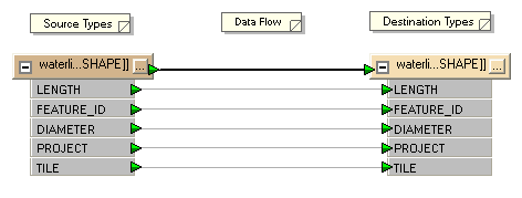
In FME Workbench, feature mapping connections (or links) are shown with a thick, black arrow.
Attribute mapping connections are shown with a thinner, grey arrow.
In Workbench, attribute mapping is sometimes implied rather than visualized, and no connecting arrow is shown. The color of the port indicates the connection status. Green indicates a connected attribute. Yellow indicates a source attribute unconnected to a destination, and red indicates a destination attribute that is not connected to a source.
Attributes with the same name in source and destination are automatically connected.
Note: The name is case-sensitive, so ROADS is not the same as roads or Roads.
In most cases, FME automatically fills in basic schema mapping in a new workspace. The schema mapping can then be edited as required.
In Workbench’s intuitive interface, feature type and attribute connections are made by dragging connecting lines between these parts of the schema.
Feature Mapping is carried out by clicking on the output port of a source feature type, dragging the arrowhead across to the input port of a destination feature type, and releasing the mouse button.
Right: Here a connecting line from source to destination feature type is being created by dragging the arrowhead from source to destination.
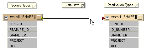
Attribute Mapping is carried out by clicking on the output port of a source attribute, dragging the arrowhead to the input port of a destination attribute, and releasing the mouse button.
Left: Here feature mapping has already been carried out and attribute connections are being made.

A new connection from FEATURE_ID to ID_NUMBER is being made. LENGTH, DIAMETER, PROJECT and TILE have matching destinations so they are connected automatically (implied connection). Note the green, yellow and red color coding showing which attributes have been connected.