 Feedback
 E-mail this topic
 Print this topic
| Map projections |
Feedback
E-mail this topic
Print this topic
|
All content that can be added to ArcGIS Explorer has a coordinate system, which is used to integrate it with the other geographic data within the common coordinate framework that is the map. Coordinate systems enable you to integrate datasets within maps as well as to perform various integrated analytical operations such as overlaying data layers from disparate sources and coordinate systems.
Coordinate systems enable geographic datasets to use common locations for integration. A coordinate system is a reference system used to represent the locations of geographic features, imagery, and observations such as GPS locations within a common geographic framework.
Each coordinate system is defined by:
There are two common types of coordinate systems used in geographic information systems (GIS):
All the elements in a map layer have a specific geographic location and extent that enables them to be located on or near the earth's surface. The ability to accurately describe geographic locations is critical in both mapping and GIS. This process is called georeferencing.
Describing the correct location and shape of features requires a framework for defining real-world locations. A geographic coordinate system is used to assign geographic locations to objects. A global coordinate system of latitude-longitude is one such framework. Another is a planar or Cartesian coordinate system derived from the global framework.
Maps represent locations on the earth's surface using grids, graticules, and tic marks labeled with various ground locations (both in measures of latitude-longitude and in projected coordinate systems (such as UTM meters). The geographic elements contained in various map layers are drawn in a specific order (on top of one another) for the given map extent.
GIS datasets contain coordinate locations within a global or Cartesian coordinate system to record geographic locations and shapes.
One method for describing the position of a geographic location on the earth's surface is using spherical measures of latitude and longitude. They are measures of the angles (in degrees) from the center of the earth to a point on the earth's surface. This reference system is often referred to as a geographic coordinate system.
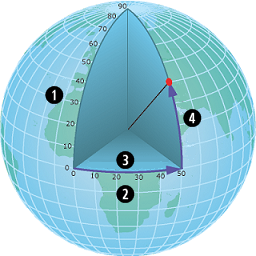 | 1. latitude 2. longitude 3. 50 degrees east 4. 40 degree north |
Latitude angles are measured in a north-south direction. The equator is at an angle of 0. Often, the northern hemisphere has positive measures of latitude and the southern hemisphere has negative measures of latitude. Longitude measures angles in an east-west direction. Longitude measures are traditionally based on the Prime Meridian, which is an imaginary line running from the North Pole through Greenwich, England to the South Pole. This angle is Longitude 0. West of the Prime Meridian is often recorded as negative Longitude and east is recorded as positive. For example, the location of Los Angeles, California is roughly Latitude "plus 33 degrees, 56 minutes" and Longitude "minus 118 degrees, 24 minutes."
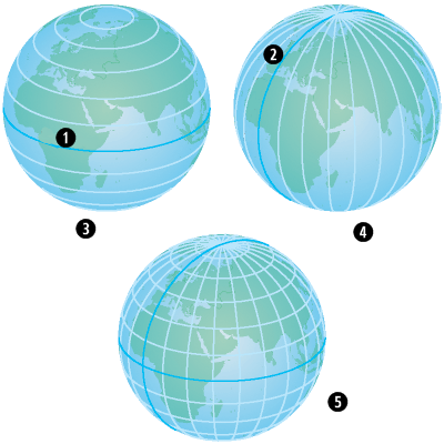 |
| 1. Equator |
| 2. Prime meridian |
| 3. Parallels: lines of latitude |
| 4. Meridians: lines of longitude |
| 5. Graticular network |
Although longitude and latitude can locate exact positions on the surface of the globe, they are not uniform units of measure. Only along the equator does the distance represented by one degree of longitude approximate the distance represented by one degree of latitude. This is because the equator is the only parallel as large as a meridian. (Circles with the same radius as the spherical earth are called great circles. The equator and all meridians are great circles.)
Above and below the equator, the circles defining the parallels of latitude get gradually smaller until they become a single point at the North and South Poles where the meridians converge. As the meridians converge toward the poles, the distance represented by one degree of longitude decreases to zero. On the Clarke 1866 spheroid, one degree of longitude at the equator equals 111.321 km, while at 60° latitude, it is only 55.802 km. Since degrees of latitude and longitude don't have a standard length, you can't measure distances or areas accurately or display the data easily on a flat map or computer screen. Performing GIS analysis and mapping applications requires a more stable coordinate framework, which is provided by projected coordinate systems.
Projected coordinate systems are any coordinate system designed for a flat surface, such as a printed map or a computer screen.
2D and 3D Cartesian coordinate systems provide the mechanism for describing the geographic location and shape of features using x and y values (and, as you will read later, by using columns and rows in rasters).
The Cartesian coordinate system uses two axes: one horizontal (x), representing east-west, and one vertical (y), representing north-south. The point at which the axes intersect is called the origin. Locations of geographic objects are defined relative to the origin, using the notation (x,y), where x refers to the distance along the horizontal axis, and y refers to the distance along the vertical axis. The origin is defined as (0,0).
In the illustration below, the notation (4, 3) records a point that is four units over in x and three units up in y from the origin.
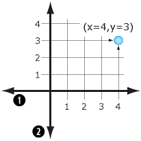 | 1. x-axis 2. y-axis |
Increasingly, projected coordinate systems also use a Z value to measure elevation above or below mean sea level.
In the illustration below, the notation (2, 3, 4) records a point that is two units over in x and three units in y from the origin and whose elevation is 4 units above the earth's surface (such as 4 meters above mean sea level).
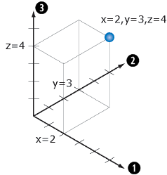 | 1. x-axis 2. y-axis 3. z-axis |
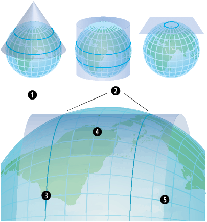
Since the earth is spherical, a challenge faced by cartographers and GIS professionals is how to represent the real world using a flat or planar coordinate system. To understand their dilemma, consider how you would flatten half of a basketball; it can't be done without distorting its shape or creating areas of discontinuity. The process of flattening the earth is called projection, hence the term map projection.
 | 1. This much earth surface has to fit onto this much map surface... |
| 2. ...therefore, much of the earth's surface has to be represented smaller than the nominal scale. | |
| 3. Projection Plane |
A projected coordinate system is defined on a flat, two dimensional surface. Projected coordinates can be defined for both 2D (x,y) and 3D (x,y,z) in which the x,y measurements represent the location on the earth's surface and z would represent height above or below mean sea level.
Below are some examples of various methods for deriving planar map projections.
 |
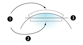
| 1. Projection plane |
| 2. Secant lines |
| 3. Secant lines are the only part of the projection plane without distortion. |
| 4. Projection distortion inside secant lines makes features slightly smaller. |
| 5. Projection distortion outside secant lines makes features slightly larger. |
Unlike a geographic coordinate system, a projected coordinate system has constant lengths, angles, and areas across the two dimensions. However, all map projections representing the earth's surface as a flat map, create distortions in some aspect of distance, area, shape, or direction.
Users cope with these limitations by using map projections that fit their intended uses, geographic location, and extent. GIS software also can transform information between coordinate systems to support integration and critical workflows.
Many map projections are designed for specific purposes. One map projection might be used for preserving shape while another might be used for preserving the area (conformal versus equal area).
These properties—the map projection (along with Spheroid and Datum), become important parameters in the definition of the coordinate system for each GIS dataset and each map. By recording detailed descriptions of these properties for each GIS dataset, computers can re-project and transform the geographic locations of dataset elements on the fly into any appropriate coordinate system. As a result, it's possible to integrate and combine information from multiple GIS layers. This is a fundamental GIS capability. Accurate location forms the basis for almost all GIS operations. ArcGIS Explorer uses the Cube map projection and the WGS 1984 spheroid.
Coordinate systems (either geographic or projected) provide a framework for defining real-world locations. In ArcGIS Explorer, the coordinate system is used as the method to automatically integrate the geographic locations from different datasets into a common coordinate framework for display and analysis.
All geographic datasets used in ArcGIS Explorer are assumed to have a well-defined coordinate system that enables them to be located in relation to the earth's surface.
If your datasets have a well-defined coordinate system, then ArcGIS Explorer can automatically integrate your datasets with others by projecting your data on the fly into the map.
If your datasets do not have a spatial reference, they cannot be integrated. You need to define one before you can use your data effectively in ArcGIS Explorer.
A spatial reference in ArcGIS Explorer is a series of parameters that define the coordinate system and other spatial properties for each dataset in the geodatabase. It is typical that all datasets for the same area (and in the same geodatabase) use a common spatial reference definition.
A spatial reference that ArcGIS Explorer can make use of includes settings for:
You or someone in your organization can create a spatial reference for existing data in ArcGIS.