- Introduction
- GET_IMAGE Request and IMAGE Response
- Zoom and Pan with ENVELOPE
- Changing the Output IMAGESIZE
- Using BACKGROUND
- LAYERLIST and LAYERDEF
- Adding Dynamic Layers
- Using Projections with GET_IMAGE
- Using LEGEND and DRAW
- Using OUTPUT to Control Image Names and Locations
Introduction
This document covers GET_IMAGE and IMAGE when using Image Services. When using ArcMap Image Services, see Using GET_IMAGE and GET_LAYOUT with ArcMap Image Services.The purpose of GET_IMAGE and IMAGE is to render a map image on the ArcIMS Spatial Server and provide the location and filename of that image. GET_IMAGE is for generating a map only. To retrieve attribute data associated with the map, a separate GET_FEATURES request must be made.
GET_IMAGE requests are sent to Image Services. The service provides a default view of the data. Using GET_IMAGE, the information in the service can be overridden. Information such as map extent or layer rendering can be modified by the request. A service can be modified in one of two ways:
- By overriding the Image Service defaults by adding new parameters in the PROPERTIES section.
- By adding dynamic layers to the Image Service using LAYER.
Image Service configuration file used with most of the GET_IMAGE requests that follow
|
<?xml version="1.0" encoding="UTF-8"?> <ARCXML version="1.1"> <CONFIG> <ENVIRONMENT> <LOCALE country="US" language="en" variant="" /> <UIFONT color="0,0,0" name="Arial" size="12" style="regular" /> </ENVIRONMENT> <MAP dynamic="true" > <PROPERTIES> <ENVELOPE minx="-180" miny="-90" maxx="180" maxy="90" name="Initial_Extent" /> <MAPUNITS units="decimal_degrees" /> <FILTERCOORDSYS id="4326" /> <FEATURECOORDSYS id="4326"/> </PROPERTIES> <WORKSPACES> <SHAPEWORKSPACE name="shp_ws-0" directory="<path to ESRIDATA>\WORLD" /> <SHAPEWORKSPACE name="shp_ws-2" directory="<path to ESRIDATA>\USA" /> <SHAPEWORKSPACE name="shp_ws-3" directory="<path to ESRIDATA>\CANADA" /> </WORKSPACES> <LAYER type="featureclass" name="Ocean" visible="true" id="0"> <DATASET name="WORLD30" type="polygon" workspace="shp_ws-0" /> <SIMPLERENDERER> <SIMPLEPOLYGONSYMBOL filltype="solid" fillcolor="0,153,255" /> </SIMPLERENDERER> </LAYER> <LAYER type="featureclass" name="Countries" visible="true" id="1"> <DATASET name="CNTRY94" type="polygon" workspace="shp_ws-0" /> <SIMPLERENDERER> <SIMPLEPOLYGONSYMBOL filltype="solid" fillcolor="255,255,153"/> </SIMPLERENDERER> </LAYER> <LAYER type="featureclass" name="States" visible="true" id="2"> <DATASET name="STATES" type="polygon" workspace="shp_ws-2" /> <SIMPLERENDERER> <SIMPLEPOLYGONSYMBOL filltype="solid" fillcolor="255,0,0" /> </SIMPLERENDERER> </LAYER> <LAYER type="featureclass" name="Provinces" visible="true" id="3"> <DATASET name="province" type="polygon" workspace="shp_ws-3" /> <SIMPLERENDERER> <SIMPLEPOLYGONSYMBOL filltype="solid" fillcolor="0,153,0" /> </SIMPLERENDERER> </LAYER> <LAYER type="featureclass" name="Cities" visible="true" id="4"> <DATASET name="CITIES" type="point" workspace="shp_ws-0" /> <SIMPLERENDERER> <SIMPLEMARKERSYMBOL color="102,0,102" width="8.0" /> </SIMPLERENDERER> </LAYER> </MAP> </CONFIG> </ARCXML> |
The following table summarizes the layer names, shapefile name, and layer ID number.
| Layer Name | Shapefile Name | Layer ID |
|---|---|---|
| Ocean | WORLD30 | 0 |
| Countries | CNTRY94 | 1 |
| States | STATES | 2 |
| Provinces | PROVINCE | 3 |
| Cities | CITIES | 4 |
GET_IMAGE Request and IMAGE Response
The simplest GET_IMAGE request includes PROPERTIES with no child elements inside. With this request, a map image is generated using default rendering and extents established in the Image Service.Simple GET_IMAGE request
|
<?xml version="1.0" encoding="UTF-8" ?> <ARCXML version="1.1"> <REQUEST> <GET_IMAGE> <PROPERTIES> </PROPERTIES> </GET_IMAGE> </REQUEST> </ARCXML> |
The IMAGE response includes a default envelope and the name and location of the generated map image.
IMAGE response
|
<?xml version="1.0" encoding="UTF8"?> <ARCXML version="1.1"> <RESPONSE> <IMAGE> <ENVELOPE minx="-180" miny="-144" maxx="180" maxy="144" /> <OUTPUT file="c:\arcims\output\world_MYCOMPUTER2102209.png" url="http://mycomputer.domain.com/output/world_MYCOMPUTER2102209.png" /> </IMAGE> </RESPONSE> </ARCXML> |
The returned map image is generated using defaults from the Image Service. The visible layers shown are Ocean, Countries, States, Provinces, and Cities. Also, the map is in geographic coordinates, and the default envelope includes the entire world.
|
Using show
When a GET_IMAGE request is made, additional information about a layer, such as the layer name, ID, and number of features sent, can be included in the response by setting the attribute show. In the next example, the attribute show="layers" is included with GET_IMAGE.GET_IMAGE request with show="layers"
|
<?xml version="1.0" encoding="UTF-8" ?> <ARCXML version="1.1"> <REQUEST> <GET_IMAGE show="layers"> <PROPERTIES> </PROPERTIES> </GET_IMAGE> </REQUEST> </ARCXML> |
The IMAGE response includes the layer information in addition to the name and location of the map image. The featurecount attribute includes only the number of features returned in the image.
IMAGE response with layer information
|
<?xml version="1.0" encoding="UTF8"?> <ARCXML version="1.1"> <RESPONSE> <IMAGE> <ENVELOPE minx="-180" miny="-135" maxx="180" maxy="135" /> <LAYERS> <LAYER name="Ocean" id="0" featurecount="72" /> <LAYER name="Countries" id="1" featurecount="165" /> <LAYER name="States" id="2" featurecount="51" /> <LAYER name="Provinces" id="3" featurecount="12" /> <LAYER name="Cities" id="4" featurecount="606" /> </LAYERS> <OUTPUT file="c:\arcims\output\world_MYCOMPUTER3633699.jpg" url="http://mycomputer.domain.com/output/world_MYCOMPUTER3633699.jpg" /> </IMAGE> </RESPONSE> </ARCXML> |
Using autoresize
During a GET_IMAGE request, the maximum size of an image can be no greater than the image memory limit set when an Image Service is started. For example, an image memory limit of 1 MB allows a map no larger than 262,144 pixels (512 x 512) to be generated. By default, an image is limited in size to 4 MB, which corresponds to 1,048,576 pixels. Changes can be made to the image size and pixel count using the ArcIMS Administrator. For more information, see ArcIMS Help.If autoresize is set to "true" in GET_IMAGE, a requested map greater than the maximum pixel count is reduced in size to within the maximum pixel count. In the next example, the Image Service image limit is 4 MB. IMAGESIZE requests an image greater than 4 MB. (IMAGESIZE is discussed in greater detail in the Changing the Output IMAGESIZE Section.)
GET_IMAGE request with autoresize="true"
|
<?xml version="1.0" encoding="UTF-8" ?> <ARCXML version="1.1"> <REQUEST> <GET_IMAGE autoresize="true"> <PROPERTIES> <IMAGESIZE width="2000" height="1600" > </PROPERTIES> </GET_IMAGE> </REQUEST> </ARCXML> |
The IMAGE response includes a resized image because the requested image size was greater than allowed. In OUTPUT, the attributes height and width show the new image size. (OUTPUT is discussed in greater detail in the Using OUTPUT to Control Image Names and Locations Section.)
IMAGE response with resized image information
|
<?xml version="1.0" encoding="UTF8"?> <ARCXML version="1.1"> <RESPONSE> <IMAGE> <ENVELOPE minx="-180" miny="-135" maxx="180" maxy="135" /> <OUTPUT file="c:\arcims\output\world_MYCOMPUTER3633699.jpg" url="http://mycomputer.domain.com/output/world_MYCOMPUTER3633699.jpg width="1086" height="965" /> </IMAGE> </RESPONSE> </ARCXML> |
If autoresize is "false" or not included in the GET_IMAGE request, and the requested image is too big, an error message is returned.
IMAGE response when requested map is too large
|
<?xml version="1.0" encoding="UTF8"?> <ARCXML version="1.1"> <RESPONSE> <ERROR machine="MYMACHINE" processid="1324" threadid="1904">[ERR0924] Requested image is too big and cannot be created.</ERROR> </RESPONSE> </ARCXML> |
Zoom and Pan with ENVELOPE
When a user pans or zooms on a map, what really happens is that the map extent changes. In a GET_IMAGE request, the extent is changed by sending new x,y minimum and maximum coordinates in an ENVELOPE. This new envelope overrides the envelope set in the Image Service. In the following example, the envelope zooms into the region around Europe.GET_IMAGE request with a change in ENVELOPE
|
<?xml version="1.0" encoding="UTF-8" ?> <ARCXML version="1.1"> <REQUEST> <GET_IMAGE> <PROPERTIES> <ENVELOPE minx="-13" miny="37" maxx="40" maxy="65" /> </PROPERTIES> </GET_IMAGE> </REQUEST> </ARCXML> |
The returned map image includes only Europe. All other information on the layers continues to use defaults from the Image Service.
|
Changing the Output IMAGESIZE
IMAGESIZE sets the size of the output map image in pixels. If IMAGESIZE is not used in a request, the default image size is 400 x 300 pixels. As noted in the using autoresize section, the maximum size of an image can be no greater than the image memory limit set when an Image Service is started.The output image sizes can be controlled three ways using the following attribute groups:
- width and height
- printwidth and printheight
- width, height, and dpi
GET_IMAGE request using IMAGESIZE
|
<?xml version="1.0" encoding="UTF-8" ?> <ARCXML version="1.1"> <REQUEST> <GET_IMAGE> <PROPERTIES> <ENVELOPE minx="-73.985" miny="40.756" maxx="-73.972" maxy="40.765" /> <IMAGESIZE width="250" height="175"/> </PROPERTIES> </GET_IMAGE> </REQUEST> </ARCXML> |
Depending on the combination of IMAGESIZE attributes and ENVELOPE size used in the request, the results of the returned map image may differ.
Width and height
Width and height are required attributes. They are used to draw a map at the specified width and height based on the envelope. If width and height are changed but the envelope remains the same, the scale of the map changes. In other words, if width and height are increased, the map is larger and, in effect, "zoomed in". If a scale threshold is met, the symbology of a layer may change or a layer might be added or removed.In the two images below, a set of streets in New York City is shown. The first map is 250 x 175 pixels in size. The second map has the same extent but is 350 x 250 pixels. Note that symbology has changed for the streets. By making the map larger, a scale threshold was met instructing the ArcIMS Spatial Server to change the street symbols.
250x175 pixels: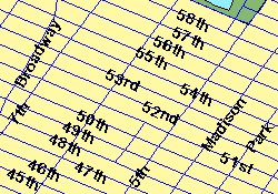 |
<PROPERTIES> <ENVELOPE minx="-73.985" miny="40.756" maxx="-73.972" maxy="40.765" /> <IMAGESIZE width="250" height="175" /> </PROPERTIES> |
350x250 pixels: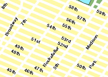 |
<PROPERTIES> <ENVELOPE minx="-73.985" miny="40.756" maxx="-73.972" maxy="40.765" /> <IMAGESIZE width="350" height="250" /> </PROPERTIES> |
Printwidth and printheight
Width, height, and dpi
To avoid having the symbology change or having layers added or removed when the map size is increased or decreased, two sets of attributes are available:
- printwidth and printheight
- width, height, and dpi.
When printwidth and printheight are used, the scale factors and dependencies are calculated based on the height and width attributes, and printwidth and printheight instruct the spatial server what size to draw the image. In the examples below, the first image has the printwidth and printheight set the same as the width and height of 250 x 175 pixels. In the second image, the width and height remain the same, but the printwidth and printheight are increased to 350 x 250 pixels. The two images contain the same content even though they are different sizes. The ratio for calculating the print map is printwidth / width. In this example the ratio is 350 / 250 or 1.4. The second map is 1.4 times the size of the original map.
When width, height, and dpi are used rather than printwidth and printheight, the final results are similar. In this case, the width and height values are changed to the desired size of the output image, or 350 x 245 pixels. To maintain the same ratio as printwidth and printheight, the dpi is set to "134". The ratio for calculating the output map is (dpi of the request) / (dpi of the Image Service). If dpi is not in the service, a default value of "96" is used. In this scenario, the dpi of the request is "134", and the dpi of the service is assumed to be "96". The ratio between the two is 134 / 96, or 1.4. This is the same ratio as the printwidth and printheight examples above, and the output image sizes are very similar in size.
| 250x175 pixels: |
<PROPERTIES> <ENVELOPE minx="-73.985" miny="40.756" maxx="-73.972" maxy="40.765" /> <IMAGESIZE width="250" height="175" printwidth="250" printheight="175" /> </PROPERTIES> <PROPERTIES> <ENVELOPE minx="-73.985" miny="40.756" maxx="-73.972" maxy="40.765" /> <IMAGESIZE width="250" height="175" /> </PROPERTIES> |
350x250 or 350x245 pixels: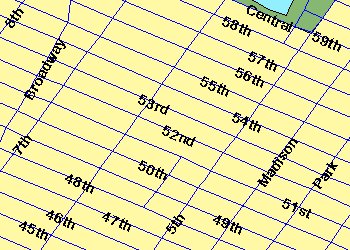 |
<PROPERTIES> <ENVELOPE minx="-73.985" miny="40.756" maxx="-73.972" maxy="40.765" /> <IMAGESIZE width="250" height="175" printwidth="350" printheight="250" scalesymbols="false" /> </PROPERTIES> <PROPERTIES> <ENVELOPE minx="-73.985" miny="40.756" maxx="-73.972" maxy="40.765" /> <IMAGESIZE width="350" height="245" dpi="134" scalesymbols="false" /> </PROPERTIES> |
In the next example, the height and width of the image is still 350 x 250 pixels, but the size of the symbology is different. In order for symbols to scale, the attribute scalesymbols must be used. By default, the symbols do not scale in size when the map size is increased or decreased. The second image below shows the map with scalesymbols set to "false", and the labels are the same size as in the first image. The third image, on the other hand, has scalesymbols set to "true". When this attribute is used, the symbols increase and decrease in size proportionally as the image size increases or decreases. In the third example below, the symbology has increased proportionally in size so that it is also 1.4 times the size of the symbology in the original map.
350x250 or 350x245 pixels: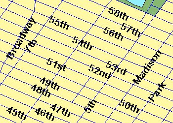 |
<PROPERTIES> <ENVELOPE minx="-73.985" miny="40.756" maxx="-73.972" maxy="40.765" /> <IMAGESIZE width="250" height="175" printwidth="350" printheight="250" scalesymbols="true" /> </PROPERTIES> <PROPERTIES> <ENVELOPE minx="-73.985" miny="40.756" maxx="-73.972" maxy="40.765" /> <IMAGESIZE width="350" height="245" dpi="134" scalesymbols="true" /> </PROPERTIES> |
Using BACKGROUND
BACKGROUND is used to define a background color for the image. It can also be used to make one color in the image transparent. Depending on the browser, the image formats that support transparent colors vary. JPG images do not support transparent colors. The table below lists which image formats support transparent colors for different browsers.| Browser | Supported Transparent Image Formats |
|---|---|
| ArcIMS HTML Viewer in Internet Explorer 5.5 or higher | PNG8, GIF |
| ArcIMS HTML Viewer in Netscape 6.2 or higher | PNG8, PNG24, GIF |
| ArcExplorer-Java Edition | PNG8, PNG24, GIF |
| ArcIMS Java Viewers in Internet Explorer and Netscape | PNG8, PNG24, GIF |
To make a color transparent, both the color and transcolor attributes of BACKGROUND must be set to the same color. In the following request, the transparent color is the blue color in the Ocean layer.
GET_IMAGE request using BACKGROUND
|
<?xml version="1.0" encoding="UTF-8" ?> <ARCXML version="1.1"> <REQUEST> <GET_IMAGE> <PROPERTIES> <ENVELOPE minx="-180" miny="-90" maxx="180" maxy="90" /> <IMAGESIZE width="500" height="400" /> <BACKGROUND color="0,153,255" transcolor="0,153,255" /> </PROPERTIES> </GET_IMAGE> </REQUEST> </ARCXML> |
In the returned image, the ocean is now transparent.
|
LAYERLIST and LAYERDEF
LAYERLIST and LAYERDEF are used together in a GET_IMAGE request to change how layers are drawn in the returned map image. Some common ways to change the layers include:- Setting layer visibility
- Changing layer symbology
- Querying a layer
- Changing layer order
Setting layer visibility
Layers in an Image Service can be switched on and off using LAYERDEF. If LAYERDEF is not included, the layer visibility is set to the visibility of the layers in the Image Service. Within the LAYERDEF element, layers that are set to visible="false" are not included in the image.The layers in LAYERDEF are identified by their ID. The following table lists which ID corresponds to which layer.
| ID | Layer Name |
|---|---|
| 0 | Ocean |
| 1 | Countries |
| 2 | States |
| 3 | Provinces |
| 4 | Cities |
In the following example, the States and Provinces layers have their visibility set to "false".
GET_IMAGE using LAYERDEF to set layer visibility
|
<?xml version="1.0" encoding="UTF-8"?> <ARCXML version="1.1"> <REQUEST> <GET_IMAGE> <PROPERTIES> <ENVELOPE minx="-180" miny="-90" maxx="180" maxy="90" /> <IMAGESIZE width="500" height="400" /> <LAYERLIST> <LAYERDEF id="0" visible="true" /> <!--Ocean--> <LAYERDEF id="1" visible="true" /> <!--Countries--> <LAYERDEF id="2" visible="false" /> <!--States--> <LAYERDEF id="3" visible="false" /> <!--Provinces--> <LAYERDEF id="4" visible="true" /> <!--Cities--> </LAYERLIST> </PROPERTIES> </GET_IMAGE> </REQUEST> </ARCXML> |
In the returned image, the States and Provinces layers are not included. Ocean, Countries, and Cities remain visible.
|
Changing layer symbology
The symbology of a layer can be changed using LAYERDEF. If no symbology information is included, then the default symbology in the Image Service is used. By adding symbology to LAYERDEF, the service information is overridden. In the next example, SIMPLERENDERER is used to change the color and symbol type for the Cities layer. The syntax for adding or modifying renderers is the same as for a map configuration file. For more information, see Using Renderers.GET_IMAGE using LAYERDEF to change layer symbology
|
<?xml version="1.0" encoding="UTF-8"?> <ARCXML version="1.1"> <REQUEST> <GET_IMAGE> <PROPERTIES> <ENVELOPE minx="-180" miny="-90" maxx="180" maxy="90" /> <IMAGESIZE width="500" height="400" /> <LAYERLIST> <LAYERDEF id="0" visible="true" /> <LAYERDEF id="1" visible="true" /> <LAYERDEF id="2" visible="false" /> <LAYERDEF id="3" visible="false" /> <LAYERDEF id="4" visible="true" > <SIMPLERENDERER> <SIMPLEMARKERSYMBOL type="star" color="155,0,0" width="12" /> </SIMPLERENDERER> </LAYERDEF> </LAYERLIST> </PROPERTIES> </GET_IMAGE> </REQUEST> </ARCXML> |
In the returned image, the Cities layer (id="4") is rendered with red stars rather than purple circles.
|
Querying a layer
Both attribute and spatial queries can be used with LAYERDEF to set a filter on a layer. For more information on using queries and buffers, see SPATIALQUERY and BUFFER.In the next example, the Cities layer includes an attribute query using SPATIALQUERY. The displayed cities are limited to those cities with a population greater than two million.
GET_IMAGE using an attribute query in LAYERDEF
|
<?xml version="1.0" encoding="UTF-8"?> <ARCXML version="1.1"> <REQUEST> <GET_IMAGE> <PROPERTIES> <ENVELOPE minx="-180" miny="-90" maxx="180" maxy="90" /> <IMAGESIZE width="500" height="400" /> <LAYERLIST> <LAYERDEF id="0" visible="true" /> <LAYERDEF id="1" visible="true" /> <LAYERDEF id="2" visible="false" /> <LAYERDEF id="3" visible="false" /> <LAYERDEF id="4" visible="true" > <SPATIALQUERY where="POPULATION > 2000000" /> <SIMPLERENDERER > <SIMPLEMARKERSYMBOL type="star" color="155,0,0" width="12" /> </SIMPLERENDERER> </LAYERDEF> </LAYERLIST> </PROPERTIES> </GET_IMAGE> </REQUEST> </ARCXML> |
In the returned image, only cities with a population greater than two million are rendered with red stars.
|
A spatial filter can also be set on a layer using SPATIALFILTER in a SPATIALQUERY. In the next example, a spatial filter is set to include only cities in Europe. In this example, ENVELOPE is used to set the filter boundary but polygons, lines, points, and buffers can also be used.
GET_IMAGE using an attribute query and spatial filter in LAYERDEF
|
<?xml version="1.0" encoding="UTF-8"?> <ARCXML version="1.1"> <REQUEST> <GET_IMAGE> <PROPERTIES> <ENVELOPE minx="-180" miny="-90" maxx="180" maxy="90" /> <IMAGESIZE width="500" height="400" /> <LAYERLIST> <LAYERDEF id="0" visible="true" /> <LAYERDEF id="1" visible="true" /> <LAYERDEF id="2" visible="false" /> <LAYERDEF id="3" visible="false" /> <LAYERDEF id="4" visible="true" > <SPATIALQUERY where="POPULATION > 2000000" > <SPATIALFILTER relation="area_intersection"> <ENVELOPE minx="-14" miny="35" maxx="33" maxy="64" /> </SPATIALFILTER> </SPATIALQUERY> <SIMPLERENDERER> <SIMPLEMARKERSYMBOL type="star" color="155,0,0" width="12" /> </SIMPLERENDERER> </LAYERDEF> </LAYERLIST> </PROPERTIES> </GET_IMAGE> </REQUEST> </ARCXML> |
In the returned image, only cities with a population greater than two million within Europe are rendered with red stars.
|
Changing the layer order of Image Service layers
The order in which Image Service layers are drawn can be changed by using the LAYERLIST attributes nodefault and order.When the attribute nodefault is set to "true", only the layers listed in the LAYERLIST are displayed. Note that when nodefault is used, the layers are always displayed in the order in which they appear in the service, even if the order of layers is changed in the LAYERLIST.
The following request has nodefault set to "true" in LAYERLIST. Since the LAYERDEF information for States and Provinces has been removed, they are not included in the map image. If nodefault were set to "false", all the layers would display even though States and Provinces are not listed.
GET_IMAGE using nodefault with LAYERLIST
|
<?xml version="1.0" encoding="UTF-8"?> <ARCXML version="1.1"> <REQUEST> <GET_IMAGE> <PROPERTIES> <ENVELOPE minx="-180" miny="-90" maxx="180" maxy="90" /> <IMAGESIZE width="500" height="400" /> <LAYERLIST nodefault="true"> <LAYERDEF id="0" visible="true" /> <!--Ocean--> <LAYERDEF id="1" visible="true" /> <!--Countries--> <LAYERDEF id="4" visible="true" > <!--Cities--> <SPATIALQUERY where="POPULATION > 2000000" > <SPATIALFILTER relation="area_intersection"> <ENVELOPE minx="-14" miny="35" maxx="33" maxy="64" /> </SPATIALFILTER> </SPATIALQUERY> <SIMPLERENDERER> <SIMPLEMARKERSYMBOL type="star" color="155,0,0" width="12" /> </SIMPLERENDERER> </LAYERDEF> </LAYERLIST> </PROPERTIES> </GET_IMAGE> </REQUEST> </ARCXML> |
The returned image is the same as the previous example. Only cities with a population greater than two million within Europe are rendered with red stars.
|
|
The layer drawing order can be changed by using the order attribute in LAYERLIST. When order is set to "true", layers are drawn in the order listed in the LAYERDEF elements. Only layers in the LAYERLIST are drawn. Note: changing the order of the layers does not affect the order in which layers are shown in a legend.
In the next example, the Cities layer (id="4") is drawn before the States (id="2") and Provinces (id="3") layers. Also, the Ocean layer (id="0") is not included in the list.
GET_IMAGE using order in LAYERLIST
|
<?xml version="1.0" encoding="UTF-8"?> <ARCXML version="1.1"> <REQUEST> <GET_IMAGE> <PROPERTIES> <ENVELOPE minx="-180" miny="-90" maxx="180" maxy="90" /> <IMAGESIZE width="500" height="400" /> <LAYERLIST order="true"> <LAYERDEF id="1" visible="true" /> <!--Countries--> <LAYERDEF id="4" visible="true" /> <!--Cities--> <LAYERDEF id="2" visible="true" /> <!--States--> <LAYERDEF id="3" visible="true" /> <!--Provinces--> </LAYERLIST> </PROPERTIES> </GET_IMAGE> </REQUEST> </ARCXML> |
In the returned image, the Ocean layer is not included, and the States and Provinces layers are drawn on top of the Cities layer.
|
Adding Dynamic Layers
Dynamic layers are added to the layers already in the existing Image Service using the GET_IMAGE request. There are two general types of dynamic layers:- For adding an existing layer in the Image Service that has been modified in some way such as showing a selected subset of data.
- For adding a new layer that is not in the service. Any LAYER type valid in a map configuration file is also valid in the GET_IMAGE request. These include point, line, polygon, image, and acetate layers.
Selecting a subset of an existing layer
Subsets of existing layers in an Image Service can be included on the map as an additional layer of information. For example, assume a user selects Brazil from the Countries layer (id="1") and wants to see it highlighted in red. Your first instinct may be to select Brazil by using a SPATIALQUERY in LAYERDEF such as in the following request. Note that the States, Provinces, and Cities layers have had their visibility turned off for better viewing.Using LAYERDEF to select Brazil
|
<?xml version="1.0" encoding="UTF-8"?> <ARCXML version="1.1"> <REQUEST> <GET_IMAGE> <PROPERTIES> <ENVELOPE minx="-180" miny="-90" maxx="180" maxy="90" /> <LAYERLIST> <LAYERDEF id="1" type="polygon" visible="true"> <SPATIALQUERY where="NAME='Brazil'" /> <SIMPLERENDERER> <SIMPLEPOLYGONSYMBOL filltype="solid" fillcolor="255,0,0"/> </SIMPLERENDERER> </LAYERDEF> <LAYERDEF id="2" visible="false" /> <LAYERDEF id="3" visible="false" /> <LAYERDEF id="4" visible="false" /> </LAYERLIST> </PROPERTIES> </GET_IMAGE> </REQUEST> </ARCXML> |
The problem with this scenario is the returned map shows only the Country of Brazil.
|
Although the above map shows the correct results, most people would expect to see all the countries with only Brazil highlighted in red. This can be done using a dynamic layer that shows Brazil as the selected country.
When setting up this type of dynamic layer, the DATASET refers back to the layer in the Image Service using its ID. In this example, DATASET fromlayer="1" refers to the Countries layer. The rest of the LAYER elements are used the same way as in a map configuration file. Each dynamic layer should have a unique ID that is not already used in the map configuration file or with other dynamic layers.
Using a dynamic LAYER to select Brazil
|
<?xml version="1.0" encoding="UTF-8"?> <ARCXML version="1.1"> <REQUEST> <GET_IMAGE> <PROPERTIES> <ENVELOPE minx="-180" miny="-90" maxx="180" maxy="90" /> <LAYERLIST> <LAYERDEF id="1" visible="true" /> <!--Countries--> <LAYERDEF id="2" visible="false" /> <!--States--> <LAYERDEF id="3" visible="false" /> <!--Provinces--> <LAYERDEF id="4" visible="false" /> <!--Cities--> </LAYERLIST> </PROPERTIES> <LAYER type="featureclass" name="Countries" visible="true" id="10"> <DATASET fromlayer="1" /> <SPATIALQUERY where="NAME='Brazil'" /> <SIMPLERENDERER> <SIMPLEPOLYGONSYMBOL filltype="solid" fillcolor="255,0,0"/> </SIMPLERENDERER> </LAYER> </GET_IMAGE> </REQUEST> </ARCXML> |
The resulting map shows two layers of countries. The bottom layer includes all the countries. The top layer includes only Brazil highlighted in red.
|
Adding new data layers dynamically
New dynamic layers can be added that include data that is not in the map configuration file. In order to add new data dynamically, the map configuration file must include dynamic="true" as part of the MAP element. In the map configuration file at the beginning of this document, dynamic is set to "true", and dynamic layers can be added in a GET_IMAGE request.|
<MAP dynamic="true" > |
Note that this attribute does not need to be set when adding a subset of an existing layer or an acetate layer.
In the next example, world rivers are added as a dynamic layer. Remember that users cannot do an identify or query on this layer. The alternative is to include the layer in the Image Service and use LAYERDEF to reference it.
To add a new layer, a WORKSPACES section must be included in the map configuration file or the request. It is recommended to always include WORKSPACES in the map configuration file since references to path names on the host computer are included. By keeping all WORKSPACES in the map configuration file, the directory locations remain hidden from users. In this example, Rivers is located in the shp_ws-0 workspace, the same workspace as for Oceans, Countries, and Cities.
Using a dynamic LAYER to add a Rivers layer
|
<?xml version="1.0" encoding="UTF-8"?> <ARCXML version="1.1"> <REQUEST> <GET_IMAGE> <PROPERTIES> <ENVELOPE minx="-180" miny="-90" maxx="180" maxy="90" /> <LAYERLIST> <LAYERDEF id="1" visible="true" /> <LAYERDEF id="2" visible="false" /> <LAYERDEF id="3" visible="false" /> <LAYERDEF id="4" visible="false" /> </LAYERLIST> </PROPERTIES> <LAYER type="featureclass" name="Rivers" visible="true" id="20"> <DATASET name="RIVERS" type="line" workspace="shp_ws-0" /> <SIMPLERENDERER> <SIMPLELINESYMBOL width="1" captype="round" color="0,0,255" /> </SIMPLERENDERER> </LAYER> <LAYER type="featureclass" name="Selected Countries" visible="true" id="10"> <DATASET fromlayer="1" /> <SPATIALQUERY where="NAME='Brazil'" /> <SIMPLERENDERER> <SIMPLEPOLYGONSYMBOL filltype="solid" fillcolor="255,0,0"/> </SIMPLERENDERER> </LAYER> </GET_IMAGE> </REQUEST> </ARCXML> |
The resulting map shows the world rivers added as a dynamic layer.
|
Adding acetate layers dynamically
Acetate layers display additional features on top of a map. The acetate layers are visible only in the HTML Viewer and viewers using the ColdFusion, ActiveX, and Java Connectors, or the .NET Link. Acetate layers do not display in ArcExplorer-Java Edition or the Java Viewers.Acetate layers are designed to show a limited number of graphic features such as a northarrow, scalebar, some text, and one or two points, lines, or polygons. The acetate layer is not designed for displaying large numbers of features. If you add many features to an acetate layer, a noticeable degradation in response time and performance is possible. If too many features are added, the service may stop responding.
Acetate layers are made up of one or more OBJECTs. The different objects include points, lines, polygons, text, north arrows, and scale bars. For details on the OBJECT element and children elements, refer to the Notes Section of OBJECT. Each object is placed on the acetate layer using screen coordinates or database coordinates. Screen coordinates are in pixels referenced from the bottom left-hand corner of the map frame. Database coordinates are in the coordinate system of the map.
In the example below, a north arrow is added using screen coordinates. "Indian Ocean" is added as text using map coordinates.
Using a dynamic LAYER to add an acetate layer
|
<?xml version="1.0" encoding="UTF-8"?> <ARCXML version="1.1"> <REQUEST> <GET_IMAGE> <PROPERTIES> <ENVELOPE minx="-180" miny="-90" maxx="180" maxy="90" /> <LAYERLIST> <LAYERDEF id="0" visible="true" /> <LAYERDEF id="1" visible="true" /> <LAYERDEF id="2" visible="false" /> <LAYERDEF id="3" visible="false" /> <LAYERDEF id="4" visible="false" /> </LAYERLIST> </PROPERTIES> <LAYER type="featureclass" name="Rivers" visible="true" id="20"> <DATASET name="RIVERS" type="line" workspace="shp_ws-0" /> <SIMPLERENDERER> <SIMPLELINESYMBOL width="1" captype="round" color="0,0,255" /> </SIMPLERENDERER> </LAYER> <LAYER type="featureclass" name="Selected Countries" visible="true" id="10"> <DATASET fromlayer="1" /> <SPATIALQUERY where="NAME='Brazil'" /> <SIMPLERENDERER> <SIMPLEPOLYGONSYMBOL filltype="solid" fillcolor="255,0,0"/> </SIMPLERENDERER> </LAYER> <LAYER type="acetate" name="acetate" id="acetate"> <OBJECT units="database"> <TEXT coords="50 -45" label="Indian Ocean"> <TEXTMARKERSYMBOL fontstyle="bolditalic" fontsize="12" /> </TEXT> </OBJECT> <OBJECT units="pixel"> <NORTHARROW type="1" size="15" coords="20 80" shadow="32,32,32" /> </OBJECT> </LAYER> </GET_IMAGE> </REQUEST> </ARCXML> |
The returned map shows three dynamic layers: Brazil as a selected country, world rivers, and the north arrow and text in the acetate layer.
|
Layer order with dynamic layers
Dynamic layers can be drawn after, before, and between service layers included in the LAYERLIST. By default, the layers are drawn in the following order:- Layers in the ArcIMS service in the order they are defined in the service including acetate layers.
- Dynamic layers added in the request in the order they are defined in the request.
| ID | Layer Name | Layer Type |
|---|---|---|
| 0 | Ocean | Image Service |
| 1 | Countries | Image Service |
| 2 | States | Image Service |
| 3 | Provinces | Image Service |
| 4 | Cities | Image Service |
| 20 | Rivers | Dynamic |
| 10 | Selected Countries | Dynamic |
| Acetate | Acetate | Dynamic |
To place all dynamic layers before the LAYERLIST, the LAYERLIST attribute dynamicfirst can be set to true. No changes need to be made in the layer order in the request but all dynamic layers are drawn first. In the next example, dynamicfirst is set to "true". In order to see the dynamic layers, the transparency of the Ocean and Countries layer has been set to 50 percent (filltransparency="0.5").
Drawing dynamic layers first using LAYERLIST dynamicfirst
|
<?xml version="1.0" encoding="UTF-8"?> <ARCXML version="1.1"> <REQUEST> <GET_IMAGE> <PROPERTIES> <ENVELOPE minx="-180" miny="-90" maxx="180" maxy="90" /> <LAYERLIST dynamicfirst="true" > <LAYERDEF id="0" type="polygon" visible="true"> <SIMPLERENDERER> <SIMPLEPOLYGONSYMBOL filltype="solid" fillcolor="0,153,255" filltransparency="0.5" /> </SIMPLERENDERER> </LAYERDEF> <LAYERDEF id="1" type="polygon" visible="true"> <SIMPLERENDERER> <SIMPLEPOLYGONSYMBOL filltype="solid" fillcolor="255,255,153" filltransparency="0.5" /> </SIMPLERENDERER> </LAYERDEF> <LAYERDEF id="2" visible="false" /> <LAYERDEF id="3" visible="false" /> <LAYERDEF id="4" visible="false" /> </LAYERLIST> </PROPERTIES> <LAYER type="featureclass" name="Rivers" visible="true" id="20"> <DATASET name="RIVERS" type="line" workspace="shp_ws-0" /> <SIMPLERENDERER> <SIMPLELINESYMBOL width="1" captype="round" color="0,0,255" /> </SIMPLERENDERER> </LAYER> <LAYER type="featureclass" name="Selected Countries" visible="true" id="10"> <DATASET fromlayer="1" /> <SPATIALQUERY where="NAME='Brazil'" /> <SIMPLERENDERER> <SIMPLEPOLYGONSYMBOL filltype="solid" fillcolor="255,0,0"/> </SIMPLERENDERER> </LAYER> <LAYER type="acetate" name="acetate" id="acetate"> <OBJECT units="database"> <TEXT coords="50 -45" label="Indian Ocean"> <TEXTMARKERSYMBOL fontstyle="bolditalic" fontsize="12" /> </TEXT> </OBJECT> <OBJECT units="pixel"> <NORTHARROW type="1" size="15" coords="20 80" shadow="32,32,32" /> </OBJECT> </LAYER> </GET_IMAGE> </REQUEST> </ARCXML> |
The returned map image shows the dynamic layers drawn first underneath the layers in LAYERLIST.
|
The drawing order of both Image Service and dynamic layers can be changed using the order attribute in LAYERLIST. If order is set to "true", only layers in LAYERLIST are drawn. They are drawn in the order in which they are listed in LAYERDEF, and the list can include dynamic layers. In the next example, Selected Countries and Rivers are placed before States and Provinces in the following order:
| ID | Layer Name | Layer Type |
|---|---|---|
| 0 | Ocean | Image Service |
| 1 | Countries | Image Service |
| 10 | Selected Countries | Dynamic |
| 20 | Rivers | Dynamic |
| 2 | States | Image Service |
| 3 | Provinces | Image Service |
| (4) | (Cities) | (Image Service) |
| Acetate | Acetate | Dynamic |
In the next example, the layers are ordered in LAYERLIST in the order in which they should appear in the image. The Cities layer is not included in the LAYERLIST and is not included in the output map image.
Using LAYERLIST order to change the order in which layers are drawn
|
<?xml version="1.0" encoding="UTF-8"?> <ARCXML version="1.1"> <REQUEST> <GET_IMAGE> <PROPERTIES> <ENVELOPE minx="-180" miny="-90" maxx="180" maxy="90" /> <LAYERLIST order="true"> <LAYERDEF id="0" visible="true" /> <LAYERDEF id="1" visible="true" /> <LAYERDEF id="10" visible="true" /> <LAYERDEF id="20" visible="true" /> <LAYERDEF id="2" visible="true" /> <LAYERDEF id="3" visible="true" /> <LAYERDEF id="acetate" visible="true" /> </LAYERLIST> </PROPERTIES> <LAYER type="featureclass" name="Rivers" visible="true" id="20"> <DATASET name="RIVERS" type="line" workspace="shp_ws-0" /> <SIMPLERENDERER> <SIMPLELINESYMBOL width="1" captype="round" color="0,0,255" /> </SIMPLERENDERER> </LAYER> <LAYER type="featureclass" name="Selected Countries" visible="true" id="10"> <DATASET fromlayer="1" /> <SPATIALQUERY where="NAME='Brazil'" /> <SIMPLERENDERER> <SIMPLEPOLYGONSYMBOL filltype="solid" fillcolor="255,0,0"/> </SIMPLERENDERER> </LAYER> <LAYER type="acetate" name="acetate" id="acetate"> <OBJECT units="database"> <TEXT coords="50 -45" label="Indian Ocean"> <TEXTMARKERSYMBOL fontstyle="bolditalic" fontsize="12" /> </TEXT> </OBJECT> <OBJECT units="pixel"> <NORTHARROW type="1" size="15" coords="20 80" shadow="32,32,32" /> </OBJECT> </LAYER> </GET_IMAGE> </REQUEST> </ARCXML> |
The returned map image shows the dynamic layers mixed in with the Image Service layers.
|
Using Projections with GET_IMAGE
The projection of an image can be changed using the projection elements: For a complete discussion on the different elements, refer to Using Projection Elements.FILTERCOORDSYS is used to specify the coordinate system of the requesting client. All the examples so far have been in geographic coordinates (decimal degrees), which have an ID of "4326". All coordinates in the request, such as those for ENVELOPE, have been in geographic coordinates.
FEATURECOORDSYS is used to specify to which coordinate system the Image Service should be transformed. In the next example, the image is requested in Robinson, which has an ID of "54030".
Using FILTERCOORDSYS and FEATURECOORDSYS
|
<?xml version="1.0" encoding="UTF-8"?> <ARCXML version="1.1"> <REQUEST> <GET_IMAGE> <PROPERTIES> <ENVELOPE minx="-180" miny="-90" maxx="180" maxy="90" /> <FILTERCOORDSYS id="4326" /> <FEATURECOORDSYS id="54030" /> <LAYERLIST> <LAYERDEF id="0" visible="true" /> <LAYERDEF id="1" visible="true" /> <LAYERDEF id="2" visible="false" /> <LAYERDEF id="3" visible="false" /> <LAYERDEF id="4" visible="false" /> </LAYERLIST> </PROPERTIES> <LAYER type="featureclass" name="Rivers" visible="true" id="20"> <DATASET name="RIVERS" type="line" workspace="shp_ws-0" /> <SIMPLERENDERER> <SIMPLELINESYMBOL width="1" captype="round" color="0,0,255" /> </SIMPLERENDERER> </LAYER> <LAYER type="featureclass" name="Selected Countries" visible="true" id="10"> <DATASET fromlayer="1" /> <SPATIALQUERY where="NAME='Brazil'" /> <SIMPLERENDERER> <SIMPLEPOLYGONSYMBOL filltype="solid" fillcolor="255,0,0"/> </SIMPLERENDERER> </LAYER> <LAYER type="acetate" name="acetate" id="acetate"> <OBJECT units="database"> <TEXT coords="50 -45" label="Indian Ocean"> <TEXTMARKERSYMBOL fontstyle="bolditalic" fontsize="12" /> </TEXT> </OBJECT> <OBJECT units="pixel"> <NORTHARROW type="1" size="15" coords="20 80" shadow="32,32,32" /> </OBJECT> </LAYER> </GET_IMAGE> </REQUEST> </ARCXML> |
In the response, the ENVELOPE coordinates are in Robinson, which was the coordinate system used in FEATURECOORDSYS.
IMAGE response with new ENVELOPE coordinates
|
<?xml version="1.0" encoding="UTF8"?> <ARCXML version="1.1"> <RESPONSE> <IMAGE> <ENVELOPE minx="-16986708.7102836" miny="-12740031.5327127" maxx="16986708.7102836" maxy="12740031.5327127" /> <OUTPUT file="C:\ArcIMS\output\world_MYCOMPUTER29852440.png" url="http://mycomputer.domain.com/output/world_MYCOMPUTER29852440.png" /> </IMAGE> </RESPONSE> </ARCXML> |
The returned map image shows the map in the Robinson coordinate system.
|
Note that the acetate OBJECT with the text "Indian Ocean" is no longer placed correctly. The problem is the OBJECT coordinate units are in geographic coordinates, while the map has been transformed to Robinson. COORDSYS can be used with an acetate OBJECT to let the ArcIMS Spatial Server know the coordinate system of the OBJECT. In the example below, COORDSYS has been added to the "Indian Ocean" object specifying the coordinates are in decimal degrees (id="4326").
Including COORDSYS in the acetate layer
|
<?xml version="1.0" encoding="UTF-8"?> <ARCXML version="1.1"> <REQUEST> <GET_IMAGE> <PROPERTIES> <ENVELOPE minx="-180" miny="-90" maxx="180" maxy="90" /> <FILTERCOORDSYS id="4326" /> <FEATURECOORDSYS id="54030" /> <LAYERLIST> <LAYERDEF id="0" visible="true" /> <LAYERDEF id="1" visible="true" /> <LAYERDEF id="2" visible="false" /> <LAYERDEF id="3" visible="false" /> <LAYERDEF id="4" visible="false" /> </LAYERLIST> </PROPERTIES> <LAYER type="featureclass" name="Rivers" visible="true" id="20"> <DATASET name="RIVERS" type="line" workspace="shp_ws-0" /> <SIMPLERENDERER> <SIMPLELINESYMBOL width="1" captype="round" color="0,0,255" /> </SIMPLERENDERER> </LAYER> <LAYER type="featureclass" name="Selected Countries" visible="true" id="10"> <DATASET fromlayer="1" /> <SPATIALQUERY where="NAME='Brazil'" /> <SIMPLERENDERER> <SIMPLEPOLYGONSYMBOL filltype="solid" fillcolor="255,0,0"/> </SIMPLERENDERER> </LAYER> <LAYER type="acetate" name="acetate" id="acetate"> <OBJECT units="database"> <COORDSYS id="4326"/> <TEXT coords="50 -45" label="Indian Ocean"> <TEXTMARKERSYMBOL fontstyle="bolditalic" fontsize="12" /> </TEXT> </OBJECT> <OBJECT units="pixel"> <NORTHARROW type="1" size="15" coords="20 80" shadow="32,32,32" /> </OBJECT> </LAYER> </GET_IMAGE> </REQUEST> </ARCXML> |
The returned image shows the map and the "Indian Ocean" OBJECT in the Robinson coordinate system.
|
Using LEGEND and DRAW
LEGEND can be used in a GET_IMAGE request to include a legend for the requested map. The legend is an additional image in the same format as the map: JPG, PNG, or GIF. DRAW can be used to request only a legend rather than both a legend and a map.The following GET_IMAGE request includes a default LEGEND since no attributes are used. DRAW has the attribute map set to "false" so that only a legend is returned.
GET_IMAGE request with LEGEND
|
<?xml version="1.0" encoding="UTF-8" ?> <ARCXML version="1.1"> <REQUEST> <GET_IMAGE> <PROPERTIES> <ENVELOPE minx="-180" miny="-90" maxx="180" maxy="90" /> <LEGEND /> <DRAW map="false" /> </PROPERTIES> </GET_IMAGE> </REQUEST> </ARCXML> |
In the response, only the name and location of the legend are included.
IMAGE response with LEGEND
|
<?xml version="1.0" encoding="UTF8"?> <ARCXML version="1.1"> <RESPONSE> <IMAGE> <LEGEND file="c:\arcims\output\world_MYCOMPUTER1248849.png" url="http://mycomputer.domain.com/output/world_MYCOMPUTER1248849.png" /> </IMAGE> </RESPONSE> </ARCXML> |
|
The returned legend image includes all layers that are currently visible in the map on a white background. |
Several attributes can be used with LEGEND to change the look and feel of the legend image. The following table shows the results of different attribute combinations.
|
When using reverseorder. The layers are in the reverse order from how they are listed in the map configuration file. <LEGEND reverseorder="true" /> |
|
When using backgroundcolor. The background color can be changed using RGB values. <LEGEND backgroundcolor="255,255,0" /> |
|
When using transcolor. One transparent color can be set using RGB values. Valid only with PNG, PNG8, and GIF formats. JPEG does not support transparency. <LEGEND transcolor="255,255,255" /> |
|
When using height. A set height in pixels can be used for the legend. Note that layer information is cut off when there is too much data to fit within the height limitation. <LEGEND height="60" /> |
|
When using autoextend. Autoextend automatically extends the legend vertically past the specified height to accommodate all the data. If height is not included, the default of 300 pixels is used for the height. If data is cut off in a legend, check if autoextend is included. <LEGEND height="60" autoextend="true" /> |
|
When using columns. Columns defines the number of columns used in the legend. In this example, the text and swatches are close together and unreadable. This is the case since the default width of 125 pixels is used. <LEGEND height="60" autoextend="true" columns="3" /> |
|
When using width. If the legend is too narrow for the layer names, the text wraps. To avoid wrapping, increase the width of the legend. <LEGEND height="60" autoextend="true" columns="3" width="300" /> |
|
When using cellspacing. Cellspacing refers to the number of pixels to pad each entry in the legend. <LEGEND cellspacing="20" /> |
|
When using title, font, and titlefontsize. A title can be added to the legend. The font and font size can also be included. The font attribute affects all text, not just the title. <LEGEND title="LEGEND" font="Times New Roman" titlefontsize="16" /> |
|
When using layerfontsize. The layer font size can be increased or decreased. The layer font is set using the font attribute. The font color cannot be changed. <LEGEND title="LEGEND" font="Times New Roman" titlefontsize="16" layerfontsize="12" /> |
|
When using swatchheight and swatchwidth. The size of the swatch representing each layer can be increased or decreased using swatchheight and swatchwidth. Measurements are in pixels. <LEGEND title="LEGEND" font="Times New Roman" titlefontsize="16" swatchheight="20" swatchwidth="20" /> |
|
When using cansplit and splittext. Cansplit and splittext are valid with layers that include a VALUEMAPRENDERER. Cansplit allows the valuemap swatches and text to be carried over into the next column. Splittext is the continuation text at the bottom of the column. <LEGEND title="LEGEND" font="Times New Roman" titlefontsize="16" layerfontsize="12" columns="3" cansplit="true" splittext="(more)" width="300" autoextend="true" /> |
|
When using valuefontsize. The font size of valuemap text can be controlled using valuefontsize. The font is set using the font attribute. The font color cannot be changed. <LEGEND title="LEGEND" font="Times New Roman" titlefontsize="16" layerfontsize="12" columns="3" cansplit="true" splittext="(more)" width="330" autoextend="true" valuefontsize="10" /> |
Using LAYERS with LEGEND
LAYERS is used to identify which layers in a legend should NOT be included. In a GET_IMAGE request, the list can include both layers in the Image Service and dynamic layers that include DATASET. Acetate layers are never included in the legend. If LAYERS is used in a map configuration file, any LAYERS information in the request overrides the information in the map configuration file.The following two scenarios produce the same results. In Scenario 1, a map is requested first with all the layers set to a visibility of "true". A second request is then made for a legend but no map, and the layer visibility for Ocean and Countries has been set to "false".
Scenario 1, Request 1 - GET_IMAGE using LAYERDEF to set layer visibility to "true" for map
|
<?xml version="1.0" encoding="UTF-8"?> <ARCXML version="1.1"> <REQUEST> <GET_IMAGE> <PROPERTIES> <ENVELOPE minx="-180" miny="-90" maxx="180" maxy="90" /> <IMAGESIZE width="500" height="400" /> <LAYERLIST> <LAYERDEF id="0" visible="true" /> <LAYERDEF id="1" visible="true" /> <LAYERDEF id="2" visible="true" /> <LAYERDEF id="3" visible="true" /> <LAYERDEF id="4" visible="true" /> </LAYERLIST> </PROPERTIES> </GET_IMAGE> </REQUEST> </ARCXML> |
Scenario 1, Request 2 - GET_IMAGE using LAYERDEF to set the visibility of some layers to "false" for legend
|
<?xml version="1.0" encoding="UTF-8"?> <ARCXML version="1.1"> <REQUEST> <GET_IMAGE> <PROPERTIES> <ENVELOPE minx="-180" miny="-90" maxx="180" maxy="90" /> <LAYERLIST> <LAYERDEF id="0" visible="false" /> <LAYERDEF id="1" visible="false" /> <LAYERDEF id="2" visible="true" /> <LAYERDEF id="3" visible="true" /> <LAYERDEF id="4" visible="true" /> </LAYERLIST> <LEGEND title="LEGEND" backgroundcolor="255,255,0" /> <DRAW map="false" /> </PROPERTIES> </GET_IMAGE> </REQUEST> </ARCXML> |
Two images are returned in two separate IMAGE responses. In the first response, the map name and location is sent. In the second response, the legend name and location are sent. In the images, the map contains all layers, while the legend does not include Ocean or Countries.
|
|
|
In Scenario 2, LAYERS is used to list which layers should not be included in the legend. The advantage of using LAYERS is that both a map and a legend can be requested at the same time. The following request produces the same results as the two previous requests in Scenario 1.
Using LAYERS in a GET_IMAGE request
|
<?xml version="1.0" encoding="UTF-8"?> <ARCXML version="1.1"> <REQUEST> <GET_IMAGE> <PROPERTIES> <LEGEND backgroundcolor="255,255,0" > <LAYERS> <LAYER id="0"/> <LAYER id="1"/> </LAYERS> </LEGEND> </PROPERTIES> </GET_IMAGE> </REQUEST> </ARCXML> |
Both the map with all layers and legend with selected layers are returned in one response.
IMAGE response
|
<?xml version="1.0" encoding="UTF8"?> <ARCXML version="1.1"> <RESPONSE> <IMAGE> <ENVELOPE minx="-180" miny="-144" maxx="180" maxy="144" /> <OUTPUT file="c:\arcims\output\world_MYCOMPUTER2102209.png" url="http://mycomputer.domain.com/output/world_MYCOMPUTER2102209.png" /> <LEGEND file="c:\arcims\output\world_MYCOMPUTER1248849.png" url="http://mycomputer.domain.com/output/world_MYCOMPUTER1248849.png" /> </IMAGE> </RESPONSE> </ARCXML> |
|
|
|
Dynamic layers in a legend
Dynamic layers that contain DATASET are included in the legend. Acetate layers are never included in the legend. In the following example, a simple LEGEND is requested.Including LEGEND with dynamic layers
|
<?xml version="1.0" encoding="UTF-8"?> <ARCXML version="1.1"> <REQUEST> <GET_IMAGE> <PROPERTIES> <ENVELOPE minx="-180" miny="-90" maxx="180" maxy="90" /> <LAYERLIST> <LAYERDEF id="1" visible="true" /> <LAYERDEF id="2" visible="false" /> <LAYERDEF id="3" visible="false" /> <LAYERDEF id="4" visible="false" /> </LAYERLIST> <LEGEND /> </PROPERTIES> <LAYER type="featureclass" name="Rivers" visible="true" id="20"> <DATASET name="RIVERS" type="line" workspace="shp_ws-0" /> <SIMPLERENDERER> <SIMPLELINESYMBOL width="1" captype="round" color="0,0,255" /> </SIMPLERENDERER> </LAYER> <LAYER type="featureclass" name="Selected Countries" visible="true" id="10"> <DATASET fromlayer="1" /> <SPATIALQUERY where="NAME='Brazil'" /> <SIMPLERENDERER> <SIMPLEPOLYGONSYMBOL filltype="solid" fillcolor="255,0,0"/> </SIMPLERENDERER> </LAYER> <LAYER type="acetate" name="acetate" id="acetate"> <OBJECT units="database"> <TEXT coords="50 -45" label="Indian Ocean"> <TEXTMARKERSYMBOL fontstyle="bolditalic" fontsize="12" /> </TEXT> </OBJECT> <OBJECT units="pixel"> <NORTHARROW type="1" size="15" coords="20 80" shadow="32,32,32" /> </OBJECT> </LAYER> </GET_IMAGE> </REQUEST> </ARCXML> |
The returned map shows Ocean, Countries, Selected Countries, Rivers, and the acetate layer. All but the acetate layer are included in the legend.
|
|
|
Dynamic layers can also be suppressed in the legend by using LAYERS. In the next example, the "Selected Countries" layer (id="10") is not included.
Using LAYERS with dynamic layers
|
<?xml version="1.0" encoding="UTF-8"?> <ARCXML version="1.1"> <REQUEST> <GET_IMAGE> <PROPERTIES> <ENVELOPE minx="-180" miny="-90" maxx="180" maxy="90" /> <LAYERLIST> <LAYERDEF id="0" visible="true" /> <LAYERDEF id="1" visible="true" /> <LAYERDEF id="2" visible="false" /> <LAYERDEF id="3" visible="false" /> <LAYERDEF id="4" visible="false" /> </LAYERLIST> <LEGEND> <LAYERS> <LAYER id="10"/> </LAYERS> </LEGEND> </PROPERTIES> <LAYER type="featureclass" name="Rivers" visible="true" id="20"> <DATASET name="RIVERS" type="line" workspace="shp_ws-0" /> <SIMPLERENDERER> <SIMPLELINESYMBOL width="1" captype="round" color="0,0,255" /> </SIMPLERENDERER> </LAYER> <LAYER type="featureclass" name="Selected Countries" visible="true" id="10"> <DATASET fromlayer="1" /> <SPATIALQUERY where="NAME='Brazil'" /> <SIMPLERENDERER> <SIMPLEPOLYGONSYMBOL filltype="solid" fillcolor="255,0,0"/> </SIMPLERENDERER> </LAYER> <LAYER type="acetate" name="acetate" id="acetate"> <OBJECT units="database"> <TEXT coords="50 -45" label="Indian Ocean"> <TEXTMARKERSYMBOL fontstyle="bolditalic" fontsize="12" /> </TEXT> </OBJECT> <OBJECT units="pixel"> <NORTHARROW type="1" size="15" coords="20 80" shadow="32,32,32" /> </OBJECT> </LAYER> </GET_IMAGE> </REQUEST> </ARCXML> |
The returned map is the same as the previous example. However, the legend does not include the "Selected Countries" layer.
|
|
|
Using OUTPUT to Control Image Names and Locations
OUTPUT, when used in a GET_IMAGE request, defines the location and filename of the output map and legend image files. By default, the image output directory and URL location are determined at the time the Image Service is started. When a request is made, the ArcIMS Spatial Server assigns a filename. The name includes the Image Service name, the computer name the image was generated on, and a randomly generated number. If the service is named "world" and the computer is "MYCOMPUTER", then an example filename is "world_MYCOMPUTER1248849.png". The ArcIMS Tasker Windows service or UNIX daemon automatically deletes these generated images on a user-specified interval.OUTPUT can be used in both a map configuration file and in a request. When used in a map configuration file, the OUTPUT information overrides the output information stored when the service is started. When used in a request, OUTPUT overrides information in both the map configuration file and when the service is started. When OUTPUT is used, the output files are not automatically deleted by ArcIMS Tasker. In order for the files to be deleted, the taskfile property must be set in tasker.properties. For information on setting this property, see ArcIMS Help.
OUTPUT works with paired attributes. If one of the attributes is used, its pair is required. There are attribute pairs for both the map and legend images. Determining which pair to use depends on whether the ArcIMS Spatial Server defines the output filename or the user does. In all cases, the output directory and URL are user-specified.
| Attribute | Paired Attribute | Filename Assignment | Example: http://mycomputer/arcims/... |
|---|---|---|---|
| path | baseurl | ArcIMS assigns random filename. | world_MYCOMPUTER1248849.png |
| name | url | User assigns a filename. | myfilename.png |
| legendpath | legendbaseurl | ArcIMS assigns random filename. | world_MYCOMPUTER1248851.png |
| legendname | legendurl | User assigns a filename. | myfilename.png |
When starting an Image Service or using OUTPUT in a request, UNC pathnames are valid. For example, instead of using "c:\arcims\output", "\\myComputer\arcims\output" can be used.
ArcIMS Spatial Server assigns filename
In the following example, the ArcIMS Spatial Server assigns a filename but the user assigns the directory and URL for both the map and the legend. The map and the legend images do not need to be written to the same directory. The attribute pairs in this scenario are path-baseurl and legendpath-legendbaseurl.Note that even though legendpath and legendbaseurl are included in OUTPUT, the LEGEND element must be present to generate a legend image. If LEGEND is not included, no legend is generated. LEGEND can be included in either the map configuration file or the request.
OUTPUT when ArcIMS Spatial Server defines filename
|
<?xml version="1.0" encoding="UTF-8" ?> <ARCXML version="1.1"> <REQUEST> <GET_IMAGE> <PROPERTIES> <ENVELOPE minx="-180" miny="-90" maxx="180" maxy="90" /> <OUTPUT path="c:\arcims" baseurl="http://mycomputer.domain.com/arcims" legendpath="c:\arcims\legend" legendbaseurl="http://mycomputer.domain.com/arcims/legend" /> <LEGEND /> </PROPERTIES> </GET_IMAGE> </REQUEST> </ARCXML> |
IMAGE response
|
<?xml version="1.0" encoding="UTF8"?> <ARCXML version="1.1"> <RESPONSE> <IMAGE> <ENVELOPE minx="-180" miny="-144" maxx="180" maxy="144" /> <OUTPUT file="c:\arcims\world_MYCOMPUTER2983738.png" url="http://mycomputer.domain.com/world_MYCOMPUTER2983738.png" /> <LEGEND file="c:\arcims\legend\world_MYCOMPUTER2983739.png" url="http://mycomputer.domain.com/output/world_MYCOMPUTER2983739.png" /> </IMAGE> </RESPONSE> </ARCXML> |
User assigns filename
In the next example, the user assigns a filename, directory, and URL for both the map and the legend. The attribute pairs in this scenario are name-url and legendname-legendurl. Once again, to generate a legend, LEGEND must be included in either the map configuration file or the request.OUTPUT when user defines filename
|
<?xml version="1.0" encoding="UTF-8" ?> <ARCXML version="1.1"> <REQUEST> <GET_IMAGE> <PROPERTIES> <ENVELOPE minx="-180" miny="-90" maxx="180" maxy="90" /> <OUTPUT name="c:\arcims\mapimage.png" url="http://mycomputer.domain.com/arcims/mapimage.png" legendname="c:\arcims\legend\legendimage.png" legendurl="http://mycomputer.domain.com/arcims/legend/legendimage.png" /> <LEGEND /> </PROPERTIES> </GET_IMAGE> </REQUEST> </ARCXML> |
IMAGE response
|
<?xml version="1.0" encoding="UTF8"?> <ARCXML version="1.1"> <RESPONSE> <IMAGE> <ENVELOPE minx="-180" miny="-144" maxx="180" maxy="144" /> <OUTPUT file="c:\arcims\mapimage.png" url="http://mycomputer.domain.com/mapimage.png" /> <LEGEND file="c:\arcims\legend\legendimage.png" url="http://mycomputer.domain.com/legend/legendimage.png" /> </IMAGE> </RESPONSE> </ARCXML> |
Restricting OUTPUT
When using an ArcIMS HTML Viewer, ArcIMS Java Viewer, ArcExplorer-Java Edition, or any other client using the ArcIMS Servlet Connector, the OUTPUT element is restricted by default.- In a GET_IMAGE request, OUTPUT is ignored.
- In an IMAGE response, the attribute file is not returned. OUTPUT includes only url. The OUTPUT location is the default location specified when the Image Service was started or the location defined in the map configuration file. The ArcIMS Spatial Server assigns the filename.
These restrictions apply only when the ArcIMS Servlet Connector is used. They do not apply to the ActiveX, ColdFusion, or Java Connectors, or to the .NET Link. The OUTPUT filename extensions are restricted to *.jpg, *.png, or *.gif, regardless of whether OUTPUT is restricted or not.