- Introduction
- GET_IMAGE Request and IMAGE Response
- Zoom and Pan with ENVELOPE
- Changing the Output IMAGESIZE
- Using BACKGROUND
- Using LAYERLIST and LAYERDEF
- Adding information using LAYER
- Using Projections with GET_IMAGE
- Using LEGEND and DRAW
- Using OUTPUT to Control Image Names and Locations
Introduction
This document covers GET_IMAGE and IMAGE when using ArcMap Image Services. When using Image Services, see Using GET_IMAGE and IMAGE with Image Services.The purpose of GET_IMAGE and IMAGE is to render a map image on the ArcIMS Spatial Server and provide the location and filename of that image. GET_IMAGE is for generating a map only. To retrieve attribute data associated with the map, a separate GET_FEATURES request must be made.
ArcMap documents contain one or more data frames, which can be viewed as a map or in a layout. For infomation on using layouts, see Using GET_LAYOUT and LAYOUT with ArcMap Image Services. Most of the sample requests that follow are based on an ArcMap document (*.mxd) consisting of two data frames called Layers and States. The Layers data frame has five layers from the ESRIDATA dataset. The following table summarizes the layer names, shapefile name, and layer ID number.
| Layers data frame Layer Name | Shapefile Name | Layer ID |
|---|---|---|
| Cities | CITIES | 0 |
| Provinces | PROVINCE | 1 |
| States | STATES | 2 |
| Countries | CNTRY94 | 3 |
| Ocean | WORLD30 | 4 |
The second data frame is used in some examples. This data frame is named States and contains the following layers:
| States data frame Layer Name | Shapefile Name | Layer ID |
|---|---|---|
| Cities | CITIES | 0 |
| Roads | ROADS | 1 |
| States | STATES | 2 |
GET_IMAGE Request and IMAGE Response
The simplest GET_IMAGE request includes PROPERTIES with no child elements inside. With this request, a map image is generated using information established in the ArcMap Image Service.Simple GET_IMAGE request
|
<?xml version="1.0" encoding="UTF-8" ?> <ARCXML version="1.1"> <REQUEST> <GET_IMAGE> <PROPERTIES> </PROPERTIES> </GET_IMAGE> </REQUEST> </ARCXML> |
The IMAGE response includes an envelope and the name and location of the generated map image.
IMAGE response
|
<?xml version="1.0" encoding="UTF8"?> <ARCXML version="1.1"> <RESPONSE> <IMAGE> <ENVELOPE minx="-180" miny="-144" maxx="180" maxy="144" /> <OUTPUT url="http://mycomputer.domain.com/output/world_MYCOMPUTER2102209.png" /> </IMAGE> </RESPONSE> </ARCXML> |
The returned map image is generated using defaults from the service. The visible layers shown are Ocean, Countries, States, Provinces, and Cities. Also, the map is in geographic coordinates, and the default envelope includes the entire world.
|
Using dataframe
By default, a GET_IMAGE request accesses the active data frame. To gain access to a different data frame, the attribute dataframe is used. In the next example, the attribute dataframe="States" is included with GET_IMAGE.GET_IMAGE request with dataframe="States"
|
<?xml version="1.0" encoding="UTF-8" ?> <ARCXML version="1.1"> <REQUEST> <GET_IMAGE dataframe="States"> <PROPERTIES> </PROPERTIES> </GET_IMAGE> </REQUEST> </ARCXML> |
The returned map image includes the States data frame. The layers shown are States, Roads, and Cities. The map is in geographic coordinates, and the default envelope includes the entire United States.
|
Using autoresize
During a GET_IMAGE request, the maximum size of an image can be no greater than the image memory limit set when an ArcMap Image Service is started. For example, an image memory limit of 1 MB allows a map no larger than 262,144 pixels (512 x 512) to be generated. By default, an image is limited in size to 4 MB, which corresponds to 1,048,576 pixels. Changes can be made to the image size and pixel count using the ArcIMS Administrator. For more information, see ArcIMS Help.If autoresize is set to "true" in GET_IMAGE, a requested map greater than the maximum pixel count is reduced in size to within the maximum pixel count. In the next example, the service image limit is 4 MB. IMAGESIZE requests an image greater than 4 MB. (IMAGESIZE is discussed in greater detail in the IMAGESIZE section).
GET_IMAGE request with autoresize="true"
|
<?xml version="1.0" encoding="UTF-8" ?> <ARCXML version="1.1"> <REQUEST> <GET_IMAGE autoresize="true"> <PROPERTIES> <IMAGESIZE width="2000" height="1600" /> </PROPERTIES> </GET_IMAGE> </REQUEST> </ARCXML> |
The IMAGE response includes a resized image, because the requested image size was greater than allowed. In OUTPUT, the attributes height and width show the new image size. (OUTPUT is discussed in greater detail in the OUTPUT section).
IMAGE response with resized image information
|
<?xml version="1.0" encoding="UTF8"?> <ARCXML version="1.1"> <RESPONSE> <IMAGE> <ENVELOPE minx="-220.916666666667" miny="-176.706042824789" maxx="220.916666666667" maxy="176.706042824789" /> <OUTPUT url="http://mycomputer.domain.com/output/world_MYCOMPUTER3633699.jpg width="1619" height="1295" /> </IMAGE> </RESPONSE> </ARCXML> |
If autoresize is "false" or not included in the GET_IMAGE request, and the requested image is too big, an error message is returned.
IMAGE response when requested map is too large
|
<?xml version="1.0" encoding="UTF8"?> <ARCXML version="1.1"> <RESPONSE> <ERROR machine="MYMACHINE" processid="1324" threadid="1904">[ERR0515] Requested image is too big and cannot be created or invalid height or width were used.</ERROR> </RESPONSE> </ARCXML> |
Zoom and Pan with ENVELOPE
When a user pans or zooms on a map, what really happens is the map extent changes. In a GET_IMAGE request, the extent is changed by sending new x and y minimum and maximum coordinates in an ENVELOPE. This new envelope overrides the envelope set in the service. In the following example, the envelope zooms to the region around Europe.GET_IMAGE request with a change in ENVELOPE
|
<?xml version="1.0" encoding="UTF-8" ?> <ARCXML version="1.1"> <REQUEST> <GET_IMAGE> <PROPERTIES> <ENVELOPE minx="-13" miny="37" maxx="40" maxy="65" /> </PROPERTIES> </GET_IMAGE> </REQUEST> </ARCXML> |
The returned map image includes only Europe.
|
Changing the Output IMAGESIZE
IMAGESIZE sets the size of the output map image in pixels. If IMAGESIZE is not used in a request, the default image size is 400 x 300 pixels. As noted in the Using Autoresize section, the maximum size of an image can be no greater than the image memory limit set when a service is started.The output image sizes can be controlled in two ways using the following attribute groups:
- width and height
- width, height, and dpi
GET_IMAGE request using IMAGESIZE
|
<?xml version="1.0" encoding="UTF-8" ?> <ARCXML version="1.1"> <REQUEST> <GET_IMAGE> <PROPERTIES> <ENVELOPE minx="-73.985" miny="40.756" maxx="-73.972" maxy="40.765" /> <IMAGESIZE width="250" height="175"/> </PROPERTIES> </GET_IMAGE> </REQUEST> </ARCXML> |
Depending on the combination of IMAGESIZE attributes and ENVELOPE size used in the request, the results of the returned map image may differ.
Width and height
Width and height are required attributes. They are used to draw a map at the specified width and height based on the envelope. If width and height are changed but the envelope remains the same, the scale of the map changes. In other words, if width and height are increased, the map is larger and, in effect, "zoomed in". If a scale threshold is met, a layer might be added or removed.In the two images below, a set of streets in New York City is shown. The first map is 250 x 175 pixels in size. The second map has the same envelope but is 350 x 250 pixels. Note that symbology has changed for the streets. By making the map larger, a scale threshold was met instructing the ArcIMS Spatial Server to change to a layer with different symbology.
250x175 pixels: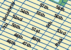 |
<PROPERTIES> <ENVELOPE minx="-73.985" miny="40.756" maxx="-73.972" maxy="40.765" /> <IMAGESIZE width="250" height="175" /> </PROPERTIES> |
350x250 pixels: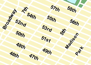 |
<PROPERTIES> <ENVELOPE minx="-73.985" miny="40.756" maxx="-73.972" maxy="40.765" /> <IMAGESIZE width="350" height="250" /> </PROPERTIES> |
Width, height, and dpi
To avoid having layers added or removed when the map size is increased or decreased, the attribute dpi can be used along with width and height.The next examples use width, height, and dpi. The first image is for reference and includes only height and width. In the second image, the width and height values are changed to the desired size of the output image, in this case 350 and 245 pixels, respectively. In order to keep the scales proportionate, a new dpi must be calculated. The formula is (new width) / (original width) * (dpi of the service). If dpi is not in the service, a default value of 96 is used. In this example, assuming a service dpi of 96, the new dpi is (350 / 250 * 96) or 134. The dpi is then set to 134.
Note that as the map size increases or decreases, the symbols scale proportionally. Whether or not symbols scale is determined at the time the ArcMap document is created.
| 250x175 pixels: |
<PROPERTIES> <ENVELOPE minx="-73.985" miny="40.756" maxx="-73.972" maxy="40.765" /> <IMAGESIZE width="250" height="175" /> </PROPERTIES> |
350x245 pixels: |
<PROPERTIES> <ENVELOPE minx="-73.985" miny="40.756" maxx="-73.972" maxy="40.765" /> <IMAGESIZE width="350" height="245" dpi="134" /> </PROPERTIES> |
Using dpi to assure correct scale thresholds
The attribute dpi can be used in IMAGESIZE, not just to accommodate new image sizes, but also to assure that scale thresholds are calculated correctly for images that do not change size. An ArcMap document can be generated using many different screen sizes. Based on the screen size, the dpi is different, and scale thresholds will differ from machine to machine. A dpi of 96 is common for screens that are 1024 x 768 pixels.The clients can also have a variety of dpi values. If a client dpi is different from the service dpi, a map will have different scale thresholds on the client. The differences are often small but sometimes noticeable.
The ArcIMS Java Viewers, ArcExplorer-Java Edition, and ArcMap can determine the dpi of a client by making system calls. These clients can include dpi in IMAGESIZE. All layer scale thresholds are recalculated each time a map is generated. The HTML Viewers, on the other hand, cannot make system calls, and therefore cannot calculate the client dpi. With the ArcIMS HTML Viewer, a dpi of 96 is assumed. If the HTML Viewer is displayed on a screen other than 96 dpi, the scale dependencies will behave differently.
Using BACKGROUND
BACKGROUND is used to define a background color for the image. It can also be used to make one color in the image transparent. Depending on the browser, the image formats that support transparent colors vary. JPG images do not support transparent colors. The table below lists which image formats support transparent colors for different browsers.| Browser | Supported Transparent Image Formats |
|---|---|
| ArcIMS HTML Viewer in Internet Explorer 5.5 or higher | PNG8, GIF |
| ArcIMS HTML Viewer in Netscape 6.2 or higher | PNG8, PNG24, GIF |
| ArcExplorer-Java Edition | PNG8, PNG24, GIF |
| ArcIMS Java Viewers in Internet Explorer and Netscape | PNG8, PNG24, GIF |
To make a color transparent, both the color and transcolor attributes of BACKGROUND must be set to the same color. In the following request, the transparent color is the blue color in the Ocean layer.
GET_IMAGE request using BACKGROUND
|
<?xml version="1.0" encoding="UTF-8" ?> <ARCXML version="1.1"> <REQUEST> <GET_IMAGE> <PROPERTIES> <ENVELOPE minx="-180" miny="-90" maxx="180" maxy="90" /> <IMAGESIZE width="500" height="400" /> <BACKGROUND color="0,153,255" transcolor="0,153,255" /> </PROPERTIES> </GET_IMAGE> </REQUEST> </ARCXML> |
In the returned image, the ocean is now transparent.
|
Using LAYERLIST and LAYERDEF
LAYERLIST and LAYERDEF are used together in a GET_IMAGE request to toggle layer visibility on and off and to set defintion queries.Using LAYERDEF visible to set layer visibility
Layers in an ArcMap Image Service can be switched on and off using the attribute visible in LAYERDEF. If LAYERDEF is not included, the layer visibility is set to the visibility of the layers in the service. Within the LAYERDEF element, layers that are set to visible="false" are not included in the image.The layers in LAYERDEF are identified by their ID. The following table lists which ID corresponds to which layer.
| ID | Layer Name |
|---|---|
| 0 | Cities |
| 1 | Provinces |
| 2 | States |
| 3 | Countries |
| 4 | Ocean |
In the following example, the States and Provinces layers have their visibility set to "false".
GET_IMAGE using LAYERDEF to set layer visibility
|
<?xml version="1.0" encoding="UTF-8"?> <ARCXML version="1.1"> <REQUEST> <GET_IMAGE> <PROPERTIES> <ENVELOPE minx="-180" miny="-90" maxx="180" maxy="90" /> <IMAGESIZE width="500" height="400" /> <LAYERLIST> <LAYERDEF id="4" visible="true" /> <!--Ocean--> <LAYERDEF id="3" visible="true" /> <!--Countries--> <LAYERDEF id="2" visible="false" /> <!--States--> <LAYERDEF id="1" visible="false" /> <!--Provinces--> <LAYERDEF id="0" visible="true" /> <!--Cities--> </LAYERLIST> </PROPERTIES> </GET_IMAGE> </REQUEST> </ARCXML> |
In the returned image, the States and Provinces layers are not included. Ocean, Countries, and Cities remain visible.
|
Using LAYERLIST order to set layer visibility
A second way to set the visibility of a layer is to use the attribute order in LAYERLIST. When order is used, only the layers listed in the LAYERLIST are included in the output. Note that with ArcMap Image Services, the layers are always displayed in the order in which they appear in the service even if the order of layers is changed in LAYERLIST.The following request has order set to "true" in LAYERLIST. Since the LAYERDEF information for States and Provinces has been removed, they are not included in the map image. Note that all layers included in LAYERLIST must have visible explicitly set to "true", or the layer will not display.
GET_IMAGE using order with LAYERLIST
|
<?xml version="1.0" encoding="UTF-8"?> <ARCXML version="1.1"> <REQUEST> <GET_IMAGE> <PROPERTIES> <ENVELOPE minx="-180" miny="-90" maxx="180" maxy="90" /> <IMAGESIZE width="500" height="400" /> <LAYERLIST order="true"> <LAYERDEF id="4" visible="true" /> <!--Ocean--> <LAYERDEF id="3" visible="true" /> <!--Countries--> <LAYERDEF id="0" visible="true" /> <!--Cities--> </LAYERLIST> </PROPERTIES> </GET_IMAGE> </REQUEST> </ARCXML> |
The returned image does not include the States or Provinces layers but does include Ocean, Countries, and Cities.

|
Using LAYERDEF to set a definition query
Attribute and spatial queries can be used in LAYERDEF to produce a subset of features. In the following example, assume a user selects Brazil from the Countries layer (id="3"). In addition to the query, a selection symbol can be used in the request but is limited to a single symbol inside SIMPLERENDERER. In this example, the symbol is a solid red SIMPLEPOLYGONSYMBOL.Using LAYERDEF to select Brazil
|
<?xml version="1.0" encoding="UTF-8"?> <ARCXML version="1.1"> <REQUEST> <GET_IMAGE> <PROPERTIES> <ENVELOPE minx="-180" miny="-90" maxx="180" maxy="90" /> <LAYERLIST> <LAYERDEF id="4" visible="true" /> <!--Ocean--> <LAYERDEF id="3" visible="true" > <!--Countries--> <SPATIALQUERY where="NAME='Brazil'" /> <SIMPLERENDERER> <SIMPLEPOLYGONSYMBOL fillcolor="255,0,0" filltype="solid"/> </SIMPLERENDERER> </LAYERDEF> <LAYERDEF id="2" visible="false" /> <!--States--> <LAYERDEF id="1" visible="false" /> <!--Provinces--> <LAYERDEF id="0" visible="false" /> <!--Cities--> </LAYERLIST> </PROPERTIES> </GET_IMAGE> </REQUEST> </ARCXML> |
In the response, only Brazil is displayed in the returned image.
|
SPATIALFILTER can also be included in LAYERDEF. The next example uses an ENVELOPE as a spatial filter to select several countries in South America.
Using a spatial filter in LAYERDEF
|
<?xml version="1.0" encoding="UTF-8"?> <ARCXML version="1.1"> <REQUEST> <GET_IMAGE> <PROPERTIES> <ENVELOPE minx="-180" miny="-90" maxx="180" maxy="90" /> <LAYERLIST> <LAYERDEF id="4" visible="true" /> <!--Ocean--> <LAYERDEF id="3" visible="true" > <!--Countries--> <SPATIALQUERY> <SPATIALFILTER relation="area_intersection"> <ENVELOPE minx="-63.6" miny="-26.9" maxx="-50.1" maxy="-8.6" /> </SPATIALFILTER> </SPATIALQUERY> <SIMPLERENDERER> <SIMPLEPOLYGONSYMBOL fillcolor="255,0,0" filltype="solid"/> </SIMPLERENDERER> </LAYERDEF> <LAYERDEF id="2" visible="false" /> <!--States--> <LAYERDEF id="1" visible="false" /> <!--Provinces--> <LAYERDEF id="0" visible="false" /> <!--Cities--> </LAYERLIST> </PROPERTIES> </GET_IMAGE> </REQUEST> </ARCXML> |
Adding Information using LAYER
An ArcMap Image Service has a defined number of layers in the service. Unlike Image Services, new data cannot be added as a dynamic layer. However, selected data sets and acetate layers can both be added in a GET_IMAGE request.Selecting features from an existing layer
Selected features from existing layers in a service can be included on a map. When setting up this type of query, a LAYER is added to the GET_IMAGE request. DATASET must be included, and the fromlayer value refers back to the LAYER id in the service.Both attribute and spatial queries can be used with LAYER to set a filter on a layer. For more information on using queries and buffers, see SPATIALQUERY, SPATIALFILTER, and BUFFER.
In the following example, the Cities layer includes an attribute query using SPATIALQUERY. The displayed cities are limited to those cities with a population greater than two million.
GET_IMAGE using an attribute query in LAYER
|
<?xml version="1.0" encoding="UTF-8"?> <ARCXML version="1.1"> <REQUEST> <GET_IMAGE> <PROPERTIES> <ENVELOPE minx="-180" miny="-90" maxx="180" maxy="90" /> <IMAGESIZE width="500" height="400" /> <LAYERLIST> <LAYERDEF id="4" visible="true" /> <LAYERDEF id="3" visible="true" /> <LAYERDEF id="2" visible="false" /> <LAYERDEF id="1" visible="false" /> <LAYERDEF id="0" visible="true" /> </LAYERLIST> </PROPERTIES> <LAYER type="featureclass" name="Cities" visible="true" id="10"> <DATASET fromlayer="0" /> <SPATIALQUERY where="POPULATION > 2000000" /> </LAYER> </GET_IMAGE> </REQUEST> </ARCXML> |
In the returned image, cities with a population greater than two million are rendered with the selection symbol defined in the ArcMap document. Selection symbols cannot be changed using SIMPLERENDERER in the request.
|
A spatial filter can also be set on a layer using SPATIALFILTER in a SPATIALQUERY. In the next example, a spatial filter is set to include only cities in Europe. ENVELOPE is used to set the filter boundary, but polygons, lines, points, and buffers could also be used.
GET_IMAGE using an attribute query and spatial filter in LAYER
|
<?xml version="1.0" encoding="UTF-8"?> <ARCXML version="1.1"> <REQUEST> <GET_IMAGE> <PROPERTIES> <ENVELOPE minx="-180" miny="-90" maxx="180" maxy="90" /> <IMAGESIZE width="500" height="400" /> <LAYERLIST> <LAYERDEF id="4" visible="true" /> <LAYERDEF id="3" visible="true" /> <LAYERDEF id="2" visible="false" /> <LAYERDEF id="1" visible="false" /> <LAYERDEF id="0" visible="true" /> </LAYERLIST> </PROPERTIES> <LAYER type="featureclass" name="Cities" visible="true" id="10"> <DATASET fromlayer="0" /> <SPATIALQUERY where="POPULATION > 2000000" > <SPATIALFILTER relation="area_intersection"> <ENVELOPE minx="-14" miny="35" maxx="33" maxy="64" /> </SPATIALFILTER> </SPATIALQUERY> </LAYER> </GET_IMAGE> </REQUEST> </ARCXML> |
In the returned image, only cities with a population greater than two million within Europe are rendered with the selection symbol defined in the ArcMap document.
|
Adding acetate layers
Acetate layers display additional features on top of a map. The acetate layers are visible only in the HTML Viewer and viewers using the ColdFusion, ActiveX, and Servlet Connectors, or the Web ADF for the Microsoft .NET Framework or Java Platform. Acetate layers do not display in ArcExplorer-Java Edition or the Java Viewers.Acetate layers are made up of one or more OBJECTs. The different objects include points, lines, polygons, text, north arrows, and scale bars. For details on the OBJECT element and its child elements, refer to the Notes section of OBJECT. Each object is placed on the acetate layer using screen coordinates or database coordinates. Screen coordinates are in pixels referenced from the lower left corner of the map frame. Database coordinates are in the coordinate system of the map.
In the example below, a north arrow is added using screen coordinates. "Indian Ocean" is added as text using map coordinates.
Using a dynamic LAYER to add an acetate layer
|
<?xml version="1.0" encoding="UTF-8"?> <ARCXML version="1.1"> <REQUEST> <GET_IMAGE> <PROPERTIES> <ENVELOPE minx="-180" miny="-90" maxx="180" maxy="90" /> <IMAGESIZE width="500" height="400" /> <LAYERLIST> <LAYERDEF id="4" visible="true" /> <LAYERDEF id="3" visible="true" /> <LAYERDEF id="2" visible="false" /> <LAYERDEF id="1" visible="false" /> <LAYERDEF id="0" visible="false" /> </LAYERLIST> </PROPERTIES> <LAYER type="acetate" name="acetate" id="acetate"> <OBJECT units="database"> <TEXT coords="50 -45" label="Indian Ocean"> <TEXTMARKERSYMBOL fontstyle="bolditalic" fontsize="12" /> </TEXT> </OBJECT> <OBJECT units="pixel"> <NORTHARROW type="1" size="50" coords="70 150" /> </OBJECT> </LAYER> </GET_IMAGE> </REQUEST> </ARCXML> |
The returned map includes the two objects from the acetate layer: the north arrow and text.
|
Layer order and acetate layers
Acetate layers are always drawn on top of the service layers. Any SCALEBAR, NORTHARROW, and TEXT objects are always drawn first before any point, line, or polygon objects. When LAYERLIST order is set to "true", the acetate layers must be included in the LAYERLIST or they will not be displayed. The next example includes the Ocean and Countries layers along with north arrow and text acetate layers. The acetate layer information is included in both the LAYER section and in the layer list.Including acetate layers in the layer list when LAYERLIST order is set to "true"
|
<?xml version="1.0" encoding="UTF-8"?> <ARCXML version="1.1"> <REQUEST> <GET_IMAGE> <PROPERTIES> <ENVELOPE minx="-180" miny="-90" maxx="180" maxy="90" /> <IMAGESIZE width="500" height="400" /> <LAYERLIST order="true" > <LAYERDEF id="4" visible="true" /> <LAYERDEF id="3" visible="true" /> <LAYERDEF id="text" visible="true" /> <LAYERDEF id="northarrow" visible="true" /> </LAYERLIST> </PROPERTIES> <LAYER type="acetate" name="text" id="text"> <OBJECT units="database"> <TEXT coords="50 -45" label="Indian Ocean"> <TEXTMARKERSYMBOL fontstyle="bolditalic" fontsize="12" /> </TEXT> </OBJECT> </LAYER> <LAYER type="acetate" name="northarrow" id="northarrow"> <OBJECT units="pixel"> <NORTHARROW type="1" size="50" coords="70 150" /> </OBJECT> </LAYER> </GET_IMAGE> </REQUEST> </ARCXML> |
Using Projections with GET_IMAGE
The projection of an image can be changed using the projection elements: For a complete discussion on the different elements, refer to Using Projection Elements.FILTERCOORDSYS is used to specify the coordinate system of the requesting client. All the examples so far have been in geographic coordinates (decimal degrees), which have an ID of "4326".
FEATURECOORDSYS is used to specify to which coordinate system the service should be transformed. In the next example, the image is requested in Robinson, which has an ID of "54030".
Using FILTERCOORDSYS and FEATURECOORDSYS
|
<?xml version="1.0" encoding="UTF-8"?> <ARCXML version="1.1"> <REQUEST> <GET_IMAGE> <PROPERTIES> <ENVELOPE minx="-180" miny="-90" maxx="180" maxy="90" /> <FILTERCOORDSYS id="4326" /> <FEATURECOORDSYS id="54030" /> <LAYERLIST> <LAYERDEF id="4" visible="true" /> <LAYERDEF id="3" visible="true" /> <LAYERDEF id="2" visible="false" /> <LAYERDEF id="1" visible="false" /> <LAYERDEF id="0" visible="false" /> </LAYERLIST> </PROPERTIES> <LAYER type="acetate" name="acetate" id="acetate"> <OBJECT units="database"> <TEXT coords="50 -45" label="Indian Ocean"> <TEXTMARKERSYMBOL fontstyle="bolditalic" fontsize="12" /> </TEXT> </OBJECT> </LAYER> </GET_IMAGE> </REQUEST> </ARCXML> |
In the response, the ENVELOPE coordinates are in Robinson, which was the coordinate system used in FEATURECOORDSYS.
IMAGE response with new ENVELOPE coordinates
|
<?xml version="1.0" encoding="UTF8"?> <ARCXML version="1.1"> <RESPONSE> <IMAGE> <ENVELOPE minx="-16986708.7102836" miny="-12740031.5327127" maxx="16986708.7102836" maxy="12740031.5327127" /> <OUTPUT url="http://mycomputer.domain.com/output/world_MYCOMPUTER29852440.png" /> </IMAGE> </RESPONSE> </ARCXML> |
The returned map image shows the map in the Robinson coordinate system.
|
Note that the acetate OBJECT with the text "Indian Ocean" is no longer placed correctly. The problem is the OBJECT coordinate units are in geographic coordinates, while the map has been transformed to Robinson. COORDSYS can be used with an acetate OBJECT to let the ArcIMS Spatial Server know the coordinate system of the OBJECT. In the example below, COORDSYS has been added to the "Indian Ocean" object specifying the coordinates are in decimal degrees (id="4326").
Including COORDSYS in the acetate layer
|
<?xml version="1.0" encoding="UTF-8"?> <ARCXML version="1.1"> <REQUEST> <GET_IMAGE> <PROPERTIES> <ENVELOPE minx="-180" miny="-90" maxx="180" maxy="90" /> <FILTERCOORDSYS id="4326" /> <FEATURECOORDSYS id="54030" /> <LAYERLIST> <LAYERDEF id="4" visible="true" /> <LAYERDEF id="3" visible="true" /> <LAYERDEF id="2" visible="false" /> <LAYERDEF id="1" visible="false" /> <LAYERDEF id="0" visible="false" /> </LAYERLIST> </PROPERTIES> <LAYER type="acetate" name="acetate" id="acetate"> <OBJECT units="database"> <COORDSYS id="4326"/> <TEXT coords="50 -45" label="Indian Ocean"> <TEXTMARKERSYMBOL fontstyle="bolditalic" fontsize="12" /> </TEXT> </OBJECT> </LAYER> </GET_IMAGE> </REQUEST> </ARCXML> |
The returned image shows the map and the "Indian Ocean" OBJECT in the Robinson coordinate system.
|
Using LEGEND and DRAW
LEGEND can be used in a GET_IMAGE request to include a legend for the requested map. The legend is an additional image in the same format as the map: BMP, GIF, JPG, PNG8, PNG24, or TIF. DRAW can be used to request only a legend rather than both a legend and a map.When using LEGEND with the ArcMap Server, the attribute autoextend should always be included and set to "true". The following GET_IMAGE request includes a default LEGEND using only the attribute autoextend. DRAW has the attribute map set to "false" so that only a legend is returned.
GET_IMAGE request with LEGEND
|
<?xml version="1.0" encoding="UTF-8" ?> <ARCXML version="1.1"> <REQUEST> <GET_IMAGE> <PROPERTIES> <ENVELOPE minx="-180" miny="-90" maxx="180" maxy="90" /> <LEGEND autoextend="true" /> <DRAW map="false" /> </PROPERTIES> </GET_IMAGE> </REQUEST> </ARCXML> |
In the response, only the name and location of the legend are included.
IMAGE response with LEGEND
|
<?xml version="1.0" encoding="UTF8"?> <ARCXML version="1.1"> <RESPONSE> <IMAGE> <LEGEND url="http://mycomputer.domain.com/output/world_MYCOMPUTER1248849.png" /> </IMAGE> </RESPONSE> </ARCXML> |
|
The returned legend image includes all layers that are currently visible in the map on a white background. |
A limitation with ArcMap Server is the height and width of a legend cannot be controlled. The height and width are only big enough to accommodate information for all layers. Text does not wrap. A legend can get quite wide as the amount of text describing a layer increases or the font size increases.
|
Several attributes can be used with LEGEND to change the look and feel of the legend image. The following table shows the results of different attribute combinations.
|
When using backgroundcolor. The background color can be changed using RGB values. <LEGEND autoextend="true" backgroundcolor="255,255,0" /> |
|
When using title, font, and titlefontsize. A title can be added to the legend. The font and font size can also be included. The font attribute affects only text in the title and is not used with the layers. <LEGEND autoextend="true" title="A Sample Legend" font="Times New Roman" titlefontsize="16" /> |
Layers do not include a value map: Layer includes a value map:  |
When using valuefontsize. For layers that include a value map, valuefontsize controls the font size of the labels that make up the value map. For layers with no value map, it controls the font size for the layer name. The font style and color cannot be changed. <LEGEND autoextend="true" title="A Sample Legend" font="Times New Roman" titlefontsize="16" valuefontsize="16" /> |

|
When using layerfontsize. Sets the font size of the subheading for layers that include a value map. The font style and color cannot be changed. In this example, the subheading is "AREA". <LEGEND autoextend="true" title="A Sample Legend" font="Times New Roman" titlefontsize="16" valuefontsize="16" layerfontsize="20" /> |
|
When using swatchheight and swatchwidth. The size of the swatch representing each layer can be increased or decreased using swatchheight and swatchwidth. Measurements are in pixels. <LEGEND autoextend="true" swatchheight="25" swatchwidth="25" /> |
Using OUTPUT to Control Image Names and Locations
When a service is started in ArcIMS Administrator, the image output directory and URL location are determined at that time. When a request is made, the ArcIMS Spatial Server assigns a filename. The name includes the service name, the computer name on which the image was generated, and a randomly generated number. If the service is named "world" and the computer is "MYCOMPUTER", then an example filename is "world_MYCOMPUTER1248849.png". ArcIMS Tasker automatically deletes these generated images on a user-specified interval.When OUTPUT is used in a GET_IMAGE request, it can be used to override location information from when the service was started. An important note is that the output files are not automatically deleted by ArcIMS Tasker. In order for the files to be deleted, the taskfile property must be set in tasker.properties. For information on setting this property, see ArcIMS Help.
OUTPUT works with paired attributes. If one of the attributes is used, its pair is required. There are attribute pairs for both the map and legend images. Determining which pair to use depends on whether the ArcIMS Spatial Server defines the output filename or the user does. In all cases, the output directory and URL are user-specified.
| Attribute | Paired Attribute | Filename assignment | Example: http://mycomputer/arcims/... |
|---|---|---|---|
| path | baseurl | ArcIMS assigns random filename. | world_MYCOMPUTER1248849.png |
| name | url | User assigns a filename. | myfilename.png |
| legendpath | legendbaseurl | ArcIMS assigns random filename. | world_MYCOMPUTER1248851.png |
| legendname | legendurl | User assigns a filename. | myfilename.png |
When starting a service or using OUTPUT in a request, UNC pathnames are valid. For example, instead of using "c:\arcims\output", "\\myComputer\arcims\output" can be used.
ArcIMS Spatial Server assigns filename
In the following example, the ArcIMS Spatial Server assigns a filename, but the user assigns the directory and URL for both the map and the legend. The map and the legend images do not need to be written to the same directory. The attribute pairs in this scenario are path-baseurl and legendpath-legendbaseurl.Note that even though legendpath and legendbaseurl are included in OUTPUT, the LEGEND element must also be present to generate a legend image. If LEGEND is not included, no legend is generated.
OUTPUT when ArcIMS Spatial Server defines filename
|
<?xml version="1.0" encoding="UTF-8" ?> <ARCXML version="1.1"> <REQUEST> <GET_IMAGE> <PROPERTIES> <ENVELOPE minx="-180" miny="-90" maxx="180" maxy="90" /> <OUTPUT path="c:\arcims" baseurl="http://mycomputer.domain.com/arcims" legendpath="c:\arcims\legend" legendbaseurl="http://mycomputer.domain.com/arcims/legend" /> <LEGEND /> </PROPERTIES> </GET_IMAGE> </REQUEST> </ARCXML> |
IMAGE response
|
<?xml version="1.0" encoding="UTF8"?> <ARCXML version="1.1"> <RESPONSE> <IMAGE> <ENVELOPE minx="-180" miny="-144" maxx="180" maxy="144" /> <OUTPUT url="http://mycomputer.domain.com/world_MYCOMPUTER2983738.png" /> <LEGEND url="http://mycomputer.domain.com/output/world_MYCOMPUTER2983739.png" /> </IMAGE> </RESPONSE> </ARCXML> |
User assigns filename
In the next example, the user assigns a filename, directory, and URL for both the map and the legend. The attribute pairs in this scenario are name-url and legendname-legendurl.OUTPUT when user defines filename
|
<?xml version="1.0" encoding="UTF-8" ?> <ARCXML version="1.1"> <REQUEST> <GET_IMAGE> <PROPERTIES> <ENVELOPE minx="-180" miny="-90" maxx="180" maxy="90" /> <OUTPUT name="c:\arcims\mapimage.png" url="http://mycomputer.domain.com/arcims/mapimage.png" legendname="c:\arcims\legend\legendimage.png" legendurl="http://mycomputer.domain.com/arcims/legend/legendimage.png" /> <LEGEND /> </PROPERTIES> </GET_IMAGE> </REQUEST> </ARCXML> |
IMAGE response
|
<?xml version="1.0" encoding="UTF8"?> <ARCXML version="1.1"> <RESPONSE> <IMAGE> <ENVELOPE minx="-180" miny="-144" maxx="180" maxy="144" /> <OUTPUT url="http://mycomputer.domain.com/mapimage.png" /> <LEGEND url="http://mycomputer.domain.com/legend/legendimage.png" /> </IMAGE> </RESPONSE> </ARCXML> |
Restricting OUTPUT
When using an ArcIMS HTML Viewer, ArcIMS Java Viewer, ArcExplorer-Java Edition, or any other browser using the ArcIMS Servlet Connector, the OUTPUT element is restricted by default.- In a GET_IMAGE request, OUTPUT is ignored.
- In an IMAGE response, the attribute file in OUTPUT is not returned; only url is included. The OUTPUT location is the default location specified when the service was started. The ArcIMS Spatial Server assigns the filename.
These restrictions apply only when the ArcIMS Servlet Connector is used.
These restrictions apply only when the ArcIMS Servlet Connector is used. They do not apply to the ActiveX, ColdFusion, or Java Connectors, or to the .NET Link. The OUTPUT filename extensions are restricted to *.gif, *.bmp, *.jpg, *.png, or *.tif, regardless of whether OUTPUT is restricted or not.